

Overview
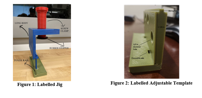
AMBICO, a specialized door making company, is trying to improve their process of marking, drilling, and tapping holes in their doors to place the hinges, which is currently done by hand. The lack of efficiency in this process can lead to delays in manufacturing for the company, due to any potential mistakes made when doing the process by hand. A need exists for an enhancement to AMBICO's hinge installation process by developing an efficient, cost-effective jig that facilitates faster and error-free marking, drilling, and tapping of holes in doors, addressing the current manual method's inefficiencies and potential manufacturing delays. This screw clamp-based jig is simple and efficient like no other, with fast set up times that streamline the entire process. With the large body that surpasses the tallest door back set, the screw can accommodate for any different back set selection. Additionally, the use of insertable templates allows the jig to match the hole configurations of any hinge dimension, and to protect any door from damage due to the clamp, the jig possesses a rubber stopper.
BOM (Bill of Materials)
|
Item |
Description |
Units |
Quantity |
Cost |
Extended Cost |
Links |
|
Rubber stopper |
To cushion the door and prevent the screw from damaging it during clamping |
Units |
1* |
11 |
16 |
|
|
Steel |
(44k psi yield strength, Rockwell B90 medium hardness, ASTM A109 specs) To make the jig body hard(excluding the screw) |
Area |
1” x 10 feet
|
19 |
26 |
|
|
Bushings |
Will be put in the holes of them templates to minimize wear and tear during drilling |
Units |
8 |
47 |
56 |
|
|
Production cost (before taxes and shipping) |
77 |
|||||
|
Production cost (After taxes and shipping) |
98 |
|||||
- Table 1.0: Bill of Materials
* - Comes in packs of 8; cost efficient to make multiple at a time.
Product Documentation
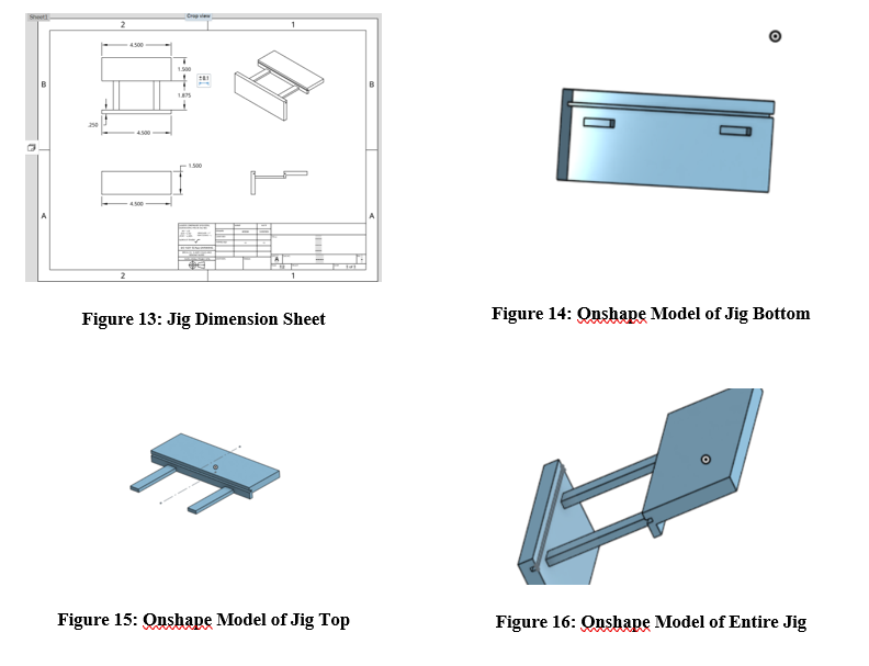
Design considerations that were considered were lack of damage to wood veneer on the door and ease of use. To avoid damaging the door while still clamping securely onto the door, the screw used to clamp onto the door was made to be wide to spread out the force of compression. A rubber pad was also added to the end of the screw to add further support and force absorption. For ease of use, the clamp was made of minimal parts and shapes. The clamp itself was shaped to fit over the door with the hinge attachment slid into place. The body of the clamp could very feasibly remain made of PLA as it is a relatively durable material while also being inexpensive and easy to use within 3D printers so that the jig can be remade in quick succession in house instead of with steel which will introduce further costs to the use of the jig. The holes on the hinge attachments must be either oversized or filled with tool steel bushings to assure that they are usable for an extended amount of time. The rubber pad itself can be replaced with any other rubber pad that will fit on the end of the screw and maintain its ability to spread out the force of compression as much as possible. In order to construct the jig, simply attach the pieces labelled in figure 14 and 15.
Conclusions and Recommendations for Future Work
Designing a drilling jig is a complex and challenging engineering project. We have learned from this experience that regular testing and iteration to identify and correct design flaws in a timely manner can avoid greater costs at a later stage. Maintaining close contact with users and ensuring that their feedback is incorporated into the design and improvement process improves product user satisfaction. Effective communication among team members is critical to solving problems and moving the project forward. Conducting a more in-depth cost analysis early in the project ensures that manufacturing costs are considered in the design to avoid unnecessary expenses later on.
If we had a few months to spare, we could have conducted market research to ensure that our product was competitive, and detailed raw material testing to ensure that all the properties of the chosen materials would meet the requirements. Then, there is the additional user survey to get more comprehensive user feedback. Due to lack of time, we forgo detailed raw material testing and additional user surveys.
Overall, ensuring flexibility in the design and refinement process, responding to user feedback in a timely manner, and focusing on teamwork contributed to the success of the project.