

Introduction
A vital aspect of engineering that we as students have limited exposure to within our degrees is applying the theory we are introduced to into a design project. This semester our team has been given the chance to do just that through the Bridge Design project. As a team we have been tasked with the responsibility of developing a conceptual design of a truss and using provided materials to bring the design to life. Up to this point in the semester as can be seen below in this document, our team researched a variety of truss designs before eventually deciding to develop a Baltimore truss. With our selected design chosen and verified within the project constraints, we used both theories developed in class as well as online software programs to analyze the reactions within the truss and verify its strength. Our truss must span 750mm between two simple supports, have a maximum height of 250 mm, and a width of 150-250 mm. The primary goal of the truss is to withstand the highest load to weight ratio (efficiency factor), which will be verified through a concentrated loading test using a 250x250 mm bearing plate placed at the mid-span of the top of our truss. With our design and analysis complete, as well as our calculated reactions, our team will now begin to analyze our materials (Balsa wood) and eventually construct our design before completing tests upon it.
Our Design
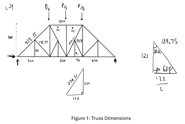
Our group selected the Baltimore truss to analyze. We chose this both due to its uniqueness and ability to very effectively resist downward forces. Furthermore, due to the large amount of zero force members it is extremely stable. As seen below, the truss will have a length of 750 mm with simple supports (roller and pin), a width between 150 mm and 250 mm, and a maximum height of 250 mm.
The Baltimore truss is very similar to the more commonly used Pratt truss. The main difference between the two is that the Baltimore truss has more zero-force members and uses more material, which should mean that it is able to withstand more downward force. As the goal of the project is to maximize how much force the bridge can withstand while fitting in the size constraints, the Baltimore truss seemed like a good option. The bridge will be subjected to a vertical load along the top, and to have the strongest bridge possible, we have conducted structural analysis using both hand calculations (method of joints and method of sections) and software (using SAP2000). The final step of the project will be to build the bridge using the provided materials, ensuring structural stability as predicted further in this report.
Truss Analysis
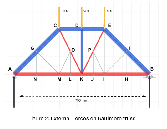
The forces that are highlighted in blue are members in compression, while those in red are under tension. If the member is not highlighted, it is a zero-force member. There are two supports, a pin (A) and a roller (B). The reaction forces are shown in black. The second reaction at A has been omitted as the reaction force is 0N in the x-direction. We assume the load (P) on the truss is 1 newton, or 1/3 N downwards at each joint C, D and E.
Written Analysis
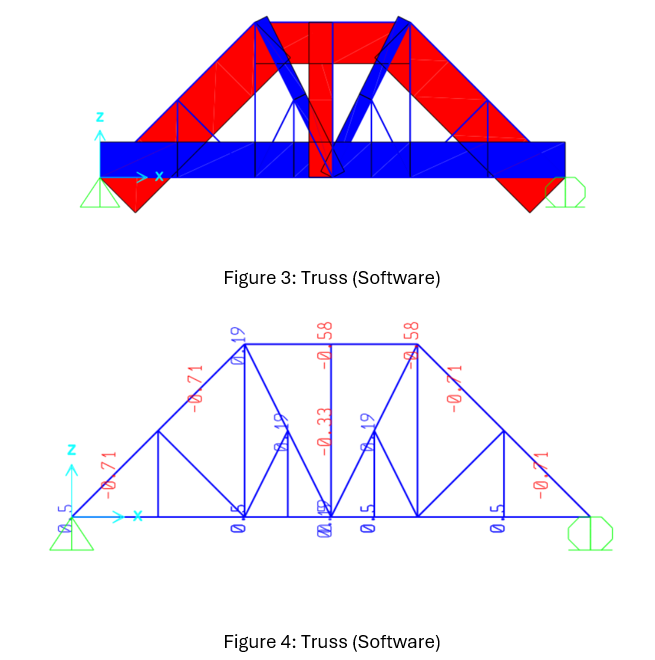
Our truss analysis presented uses both the Method of Joints and the Method of Sections to determine the internal forces acting on each member. The forces are sorted by colour, red meaning tension members and blue meaning compression members. Zero force members are also identified by grey lines, all as seen in figure 1. The calculations show that the vertical reaction force at the pin and rolling supports are both 0.5 Newtons (N). These values verify that the Baltimore truss is in static equilibrium, meaning the external loads are properly supported by the reaction forces. As for the forces around the pinned support’s side of the truss, FCD, FCO, and FML are tension forces, whereas FFB and FGA are compression forces. This distribution of forces aligns with the expectations for our truss, since diagonal members tend to face compressive forces, while vertical members likely have tension forces. Additionally, CM, EI, FH, FI, GM, GN, LO, PI, PJ are zero force members, and act as stabilizers to prevent any deformation from external loads. The forces acting on the members are within reasonable limits, which suggests that the Baltimore truss can handle the tested load.
Conclusion
In conclusion, our team has determined through all three methods of analysis that the Baltimore truss is in static equilibrium and should be able to withstand a relatively large vertical load. Due to the large number of zero-force members as well as there being many members in both tension and compression, we can predict that this system will work better relative to the simpler but comparable Pratt truss, but will also weigh more, and therefore the efficiency factor may be lower. Moving forward, we will first analyze the material that will be used, in this case Balsa wood, and then construct the bridge using the tools provided to us in the lab.