PROBLEM STATEMENT
Design, build, and test a functional three band audio equalizer with an integrated power amplifier that can independently boost or attenuate low, mid, and high frequency content, then recombine the adjusted signals into a single output capable of driving a speaker. The circuit must meet performance targets for filter cutoff frequencies (within plus or minus 10 percent), adjustable output levels at key test frequencies, low output ripple, and at least 400 mW of delivered amplifier power.
BILL OF MATERIALS
| Item | Qty | Specification / notes | Purpose |
|---|---|---|---|
| Op amp IC | 1 or more | LM324 | Active filters, buffers, gain stages, and summing amplifier |
| Audio power amplifier IC | 1 | LM386 | Power amplification to drive the load or speaker |
| Potentiometers | 3 | user operated pots (one per band) | Independent gain control for low, mid, high bands |
| Resistors | set | includes values used in design and summing: 470 ohm, 47 ohm, 8.2 kOhm, 10 kOhm, 33 kOhm (plus others as needed) | Filter RC networks, amplifier feedback and input resistors, summing network |
| Capacitors | set | includes 0.1 uF and 1 uF (plus others as needed) | Filter cutoff setting, coupling, and stability |
| Speaker or load resistor | 1 | 8 ohm speaker target for requirement; 5 ohm load used for power testing | Output load for listening tests and power measurements |
| Breadboard and jumper wires | 1 set | standard lab prototyping parts | Physical circuit assembly and connections |
| Bench power supply | 1 | DC supply for op amp and LM386 stages | Provides operating power for the circuit |
| Function generator | 1 | used for sine sweep and fixed frequency tests | Input signal generation for FRA and voltage tests |
| Oscilloscope (with FRA capability if available) | 1 | used for FRA plots, ripple evaluation, and Vrms measurements | Verification of frequency response, ripple, and output amplitude |
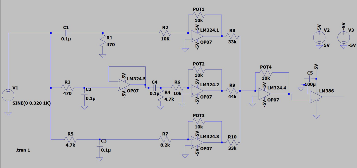
CIRCUIT DIAGRAM