

1. System Requirements & Design Objectives
The objective of this project was to design a compact, reliable mechatronic system capable of consistently launching a ball from a fixed starting position to a specified target distance while minimizing energy input and maintaining structural integrity under applied loads.
Key design requirements included:
- Accurate and repeatable ball displacement across multiple target distances
- Closed-loop control of arm position and motor speed
- Robust mechanical structure capable of handling dynamic loading
- Efficient energy usage through optimized mechanical design and control tuning
- Safe and reliable operation using commercially available components
These requirements guided all mechanical, electrical, and control system decisions throughout the project.
2. Mechanical Design & Concept Selection
Concept Development
Three mechanical launcher concepts were developed and evaluated during the conceptual design phase. Each concept used a rotating arm driven by a DC motor but differed in:
- Arm geometry and truss configuration
- Mass distribution and moment of inertia
- Ball release mechanism
- Shaft attachment and structural layout
Each concept was assessed using quantitative and qualitative criteria, including:
- Mass moment of inertia
- Deflection under load
- Axial and bending stresses
- Ease of control and manufacturability
- Compatibility with motor torque limits
A weighted decision matrix was used to objectively compare the concepts and identify the most promising design.
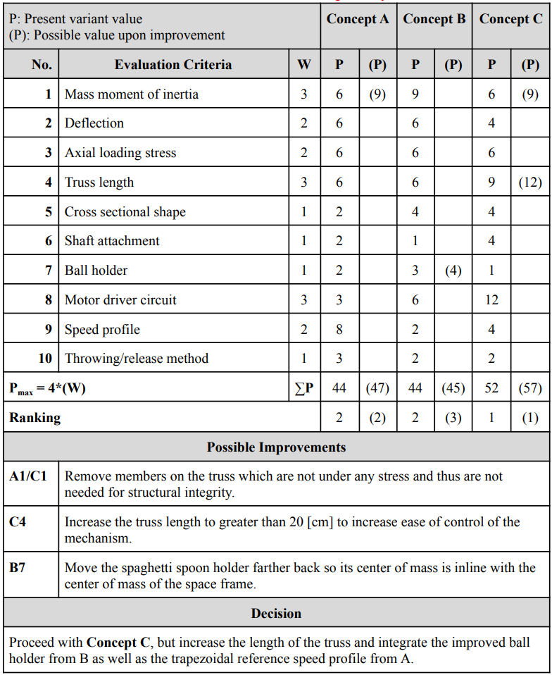
Figure 1: Concept comparison and evaluation matrix
Final Mechanical Design
The final design was selected based on its lower effective inertia, improved controllability, and structural robustness.
Key refinements included:
- Increasing truss length to improve control authority
- Removing non-load-bearing structural members to reduce mass
- Optimizing ball holder placement to align the center of mass with the arm’s rotational axis
The resulting mechanical assembly provided a good balance between stiffness, durability, and control responsiveness.
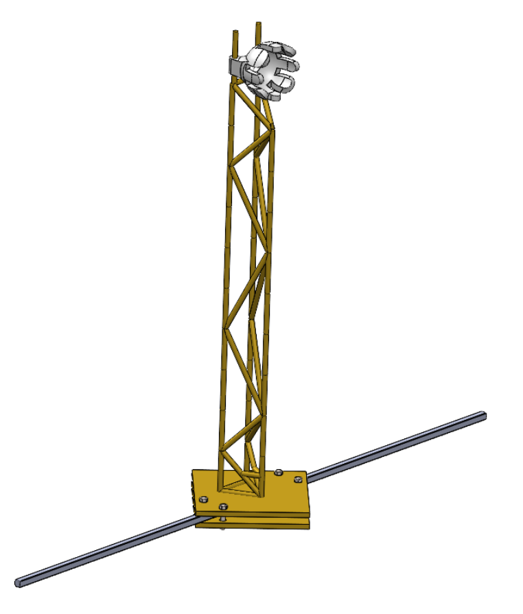
Figure 2: Final mechanical design isometric view
3. Power Electronics & Motor Drive
The launcher was driven by a brushed DC motor controlled through a custom motor drive circuit. The drive system included:
- H-bridge topology for bidirectional motor control
- Logic gate-based switching control
- Current handling considerations to meet torque requirements
- Thermal analysis to prevent component failure under high current operation
During integration, insufficient torque output was initially observed due to current limitations. This was resolved by increasing armature current within safe operating limits, highlighting the direct relationship between motor torque and current.
A key lesson learned was the importance of thermal and current protection in power electronics. An early iteration resulted in damage to an H-bridge due to excessive current, reinforcing the need for careful validation before hardware testing.

Figure 3: Motor driver circuit schematic
4. Control System Architecture
Control Strategy
The system employed a hierarchical closed-loop control architecture consisting of:
- An inner-loop speed controller
- An outer-loop position controller
Both controllers were implemented using PI control and tuned iteratively through simulation and experimental testing.
A Hall effect sensor was integrated to provide a consistent reference position for the arm. This eliminated inconsistencies caused by gravity-driven return motion and significantly improved repeatability between launches.
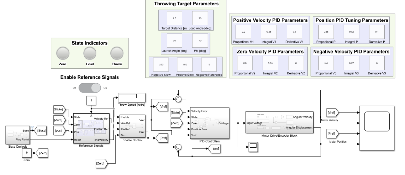
Figure 4: Control System Block Diagram
Modeling and Tuning
Motor and system dynamics were modeled using transfer functions derived from motor parameters and mechanical properties. Control tuning was performed using:
- Root locus analysis
- Bode plots
- Time-domain step response analysis
Although simulations provided a strong starting point, real-world testing revealed discrepancies due to unmodeled effects such as friction, backlash, and component variability. Final controller gains were refined experimentally to ensure stability and performance in the physical system.
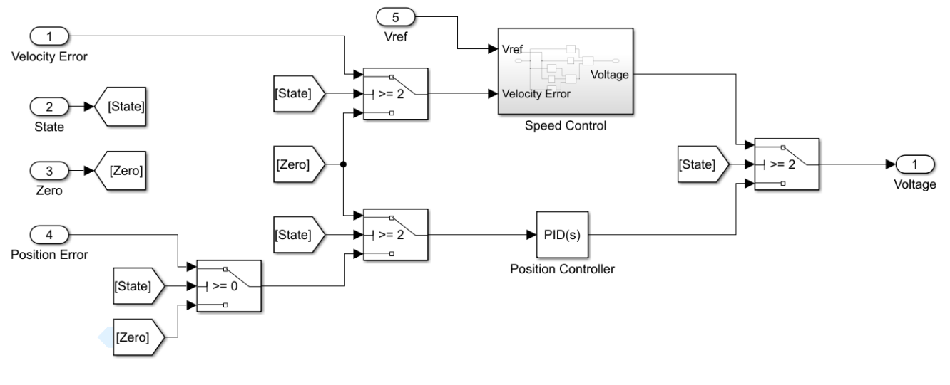
Figure 5: PID Controller Block Diagram
5. Experimental Results & Performance
The fully integrated system demonstrated:
- Consistent starting position detection using Hall effect sensing
- Stable speed and position control across multiple target distances
- Strong performance in both known and unknown target scenarios
Despite component variability between motors, the control system was robust enough to maintain acceptable performance without retuning gains for each distance. In competition testing, the system achieved its best results at previously untested distances, validating the generality of the control approach.
Measurement uncertainty from the target platform introduced some error, but overall system performance met design expectations.

Figure 6: Final assembled system and testing setup
6. Key Challenges & Engineering Lessons
Several engineering challenges were encountered and resolved:
- Inconsistent initial position: Solved using Hall effect sensor integration
- Insufficient torque: Addressed by revisiting motor current limits
- Simulation vs. reality mismatch: Resolved through iterative experimental tuning
- Component variability: Highlighted the importance of quality control in real-world systems
This project reinforced the importance of validating assumptions, designing for robustness, and iterating between simulation and physical testing.
7. Future Improvements
Potential improvements to evolve this system into a production-ready product include:
- Further optimization of arm dynamics to reduce inertia
- Advanced control strategies beyond classical PI control
- Modular enclosure for electronics and power supply
- Enhanced sensing for improved feedback accuracy
- Alternative throwing mechanisms (e.g., underhand launch option)
- Improved aesthetics and packaging for end-user deployment