

Design Process
For this class project, we designed a signal generator that is able to produce a square wave oscillating between +5V and -5V, triangle wave oscillating between +2V and -2V, and finally a sine wave oscillating between +1V and -1V, and uses no voltage source and only a single potentiometer to oscillate between 500Hz and 5kHz. We incorporated a combination of oscillators, non-inverting amplifiers, and finally a diode arrangement.
In our first attempts to construct this project, we wanted to explore the use of a Wein-Bridge Oscillator. We were able to generate our desired sine wave, but due to the sensitivity of such an oscillator, we were unsuccessful in generating an undistorted sine wave across our selected frequencies. The original design of the oscillator is seen below:

If this initial design had worked, we would have followed up with a Schmidt trigger and integrator circuit, but we did not make use of this original design. We then decided to start our circuit with a square wave, and for this, we would use the relaxation oscillator shown below, incorporating our 50kΩ potentiometer to adjust the frequency of the first square wave output. Additionally, we realised we needed to incorporate a voltage divider to reduce the amplitude of our square wave to the desired 5V.
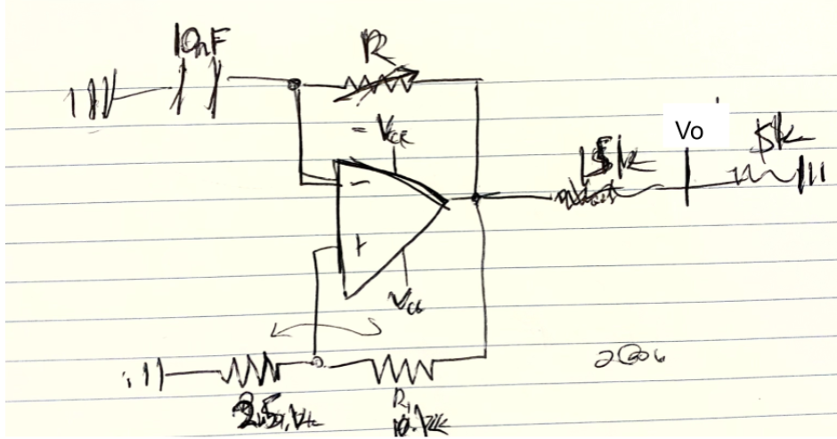
We derive an equation for the frequency of this oscillator to be:
f=1/2RCln(1+2R2/R1)
(ElectronX Lab)
We then change the subject to get an equation that is able to calculate the R value at each of the required frequencies:
R=1/2fCln(1+2R2/R1)
f=500Hz, R =45512
f=5000Hz, R =4551.2
Using the 50kΩ potentiometer, as determined by our resistance calculations, we can adjust the frequency of our waves to the regions specified in the design document. Now that we have set up our square wave, we know that an integrator circuit is all that we need to generate our triangle wave.
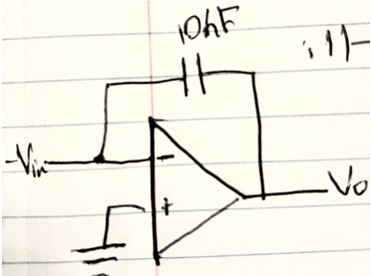
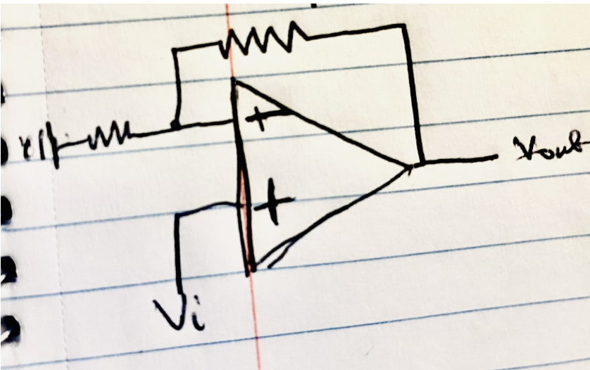
We did this and received a triangular wave that is below the required amplitude, so we employed a non-inverting amplifier to boost our input into the integrator slightly, with the design below:
Now, we need to convert our triangular wave into a sine wave. We were unsure how to do this, but after some research, we identified a method that works for us. We used the design below from Accidental Science not only to mimic sine waves but also to reduce the amplitude of our wave to the desired bounds.
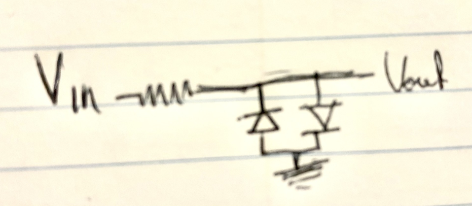
(Accidental Science)
We were now able to combine all of these into the ideal circuit diagram seen below:
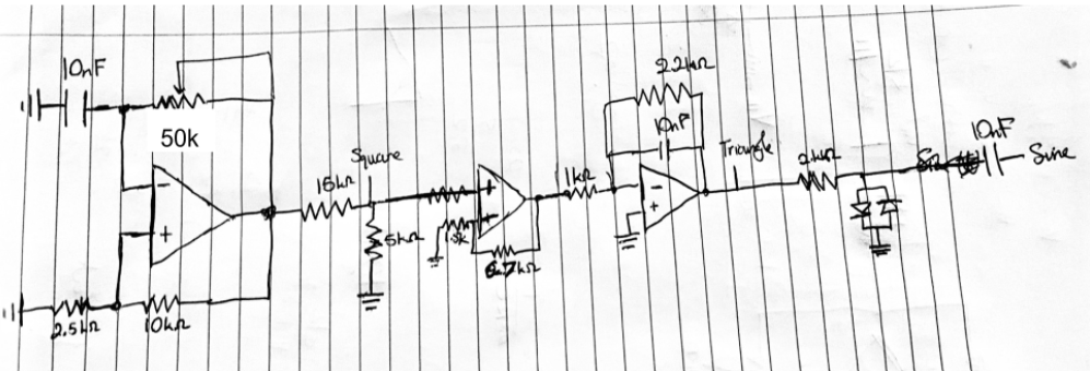
We calculated the respective gains of the operational amplifiers after the oscillator using the following non-inverting opamp formula:
Gain=1+R2/R1
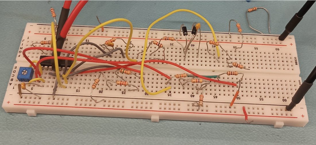
For our first opamp, the gain is 3.24 V/V, and for the integrator is -2.2 V/V. Here is our fully realised circuit, with all components assembled on a single breadboard using an LMC660C opamp. I personally built the circuit.
Results
Now, we see the effects of our circuit in action at 500Hz, 3kHz, and, finally, a frequency as close as possible to 5kHz, to show that we met the prescribed criteria for the project.
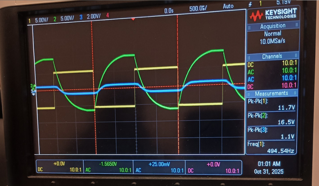
The output for our triangle wave was incorrect because we initially measured at the wrong point, but this has been corrected for all other frequencies.
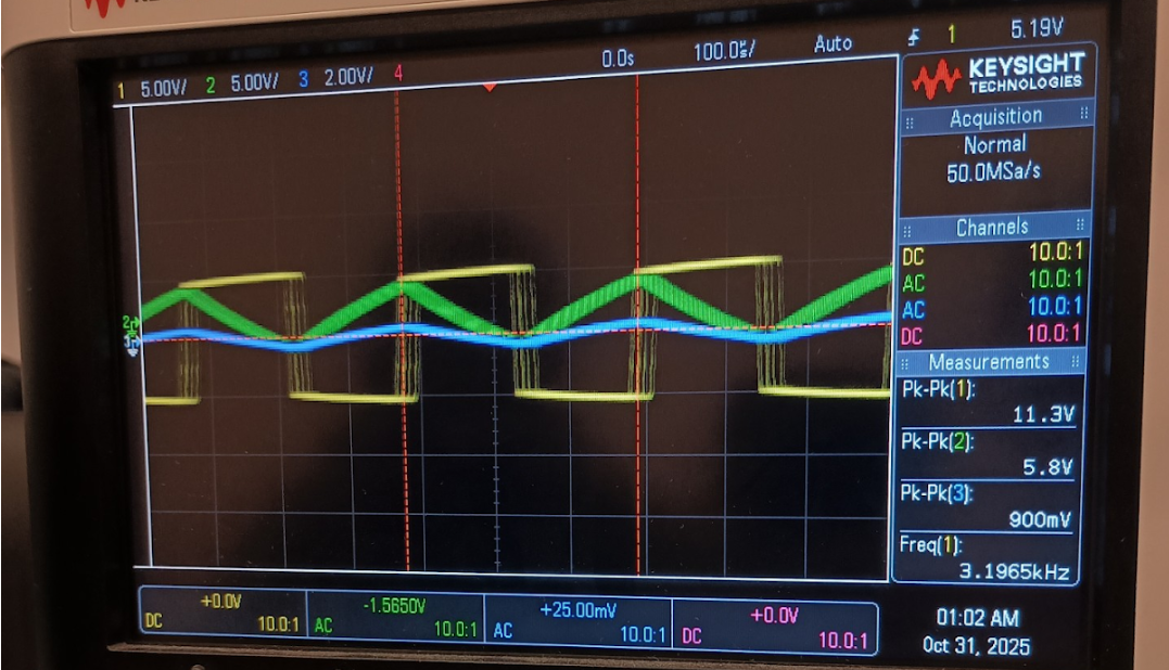
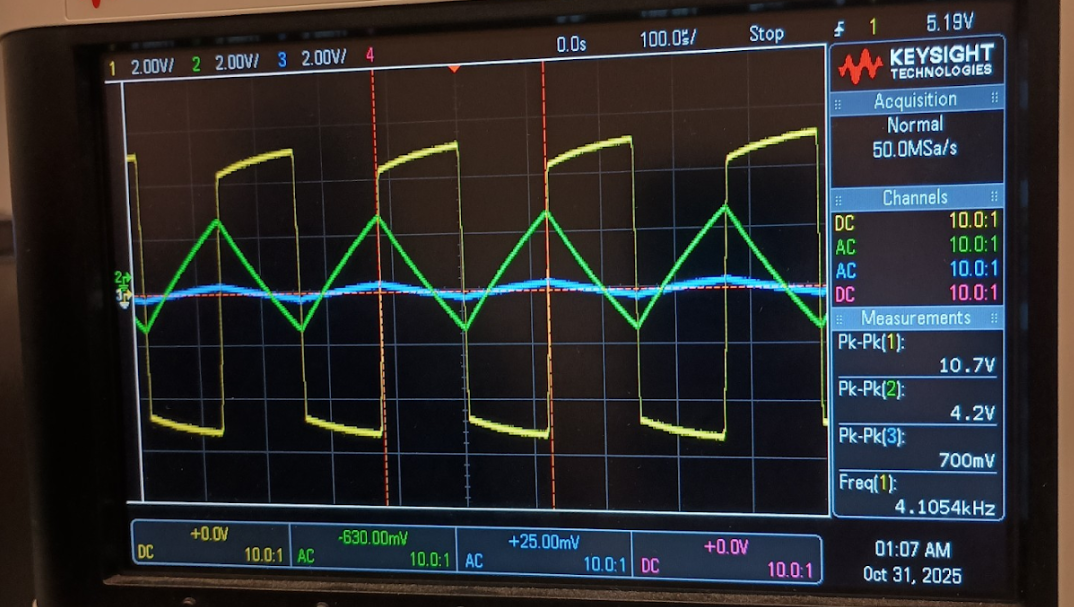
We were able to extract the desired waveforms, as shown in the above images. Measuring the required points would output each of the desired waveforms simultaneously in accordance with the setup requirements. We see some errors in the peak values due to using the nominal resistor values we had available to approximate the desired gain ratios in our circuit.
Citations
Accidental Science. “Triangle to Sine with a #Wave-Shaper #Electronic #Circuit.” YouTube, 21 Mar. 2022, www.youtube.com/watch?v=5Y2785BNzk0. Accessed 23 Oct. 2025.
ElectronX Lab. “Operational Amplifiers - Relaxation Oscillators.” YouTube, YouTube Video, 29 Mar. 2011, www.youtube.com/watch?v=QLQrLO0zvDI. Accessed 23 Oct. 2025.