project-highlight-image

Modular 3-Axis CIJ Marking System for Tubing and Vials

This project involved the ground-up design of a modular 3-axis continuous inkjet (CIJ) marking system for high-throughput marking of pharmaceutical tubing and vial-based components. The system was developed to replace legacy platforms with a more manufacturable, scalable, and cost-efficient architecture. The design integrates motion control, printhead positioning, fixturing, and electrical layout into a unified workstation optimized for repeatability, serviceability, and operator usability. A key focus was reducing reliance on machined components by leveraging aluminum extrusion structures, sheet metal panels, and functional 3D printed parts. The system supports a wide range of part geometries through adjustable fixturing and includes provisions for optional vision integration and variable printhead orientation, enabling marking across multiple axes and surfaces.
Home
Questions?
hero-image

Kevin Harry

Project Timeline

Feb 2024 - Current

HighlightS

Led full system redesign from concept to production-ready architecture

  • Transitioned from legacy designs to a modular, repeatable platform
  • Standardized mounting interfaces and structural layout


Engineered a 3-axis motion system for precise CIJ print placement

  • Designed for consistent positioning across varying cylindrical and irregular parts
  • Optimized travel envelope while maintaining a compact machine footprint


Developed modular printhead mounting system

  • Integrated adjustable theta orientation for multi-directional marking
  • Designed interchangeable head blocks for different configurations (standard and vision-ready)


Reduced manufacturing cost and complexity

  • Replaced machined components with sheet metal and PETG 3D printed parts
  • Reduced part count and simplified assembly workflow


Designed application-specific fixturing solutions

  • Created 3D printed fixtures for cylindrical and threaded components
  • Implemented repeatable alignment features for consistent marking accuracy


Integrated system-level electrical layout

  • Designed mounting strategies for controls and cable routing
  • Prioritized accessibility for maintenance and installation


Improved operator usability and safety

  • Designed ergonomic access to the work area
  • Incorporated containment strategies for ink and part handling

SKILLS

SolidWorks
Mechanical Design
Motion & Automation Systems Design
Systems Integration
DFM/DFA

Problem Statement


Laboratories require reliable identification of tubes and vials, but traditional labeling methods—such as adhesive or paper labels—are prone to peeling, degradation, and failure, especially under temperature cycling and cryogenic conditions. These methods also introduce unnecessary material waste and slow down high-throughput workflows due to manual application.

At the same time, marking directly on small, curved surfaces presents challenges in precision, legibility, and consistency. Poor alignment or ink smearing can render parts unreadable, while long drying times increase the risk of handling damage. Additionally, inks must adhere to various materials and remain durable in harsh environments, including cryogenic storage

To address these limitations, labs need a solution that enables precise, smear-resistant, and durable marking on small components, eliminates reliance on disposable labels, and supports high-throughput operation with minimal operator intervention.


Process

The system was developed through a full-cycle design approach, beginning with defining part requirements, throughput targets, and environmental constraints. A modular aluminum extrusion frame was designed to serve as the structural base, providing rigidity, scalability, and clear mounting interfaces for motion components, enclosures, and service access. Mechanical components were split between machined parts for precision-critical features and sheet metal for cost-effective structural elements, with standardized fasteners and alignment features to ensure repeatable assembly.

Motion and actuation were sized to meet positioning accuracy, speed, and load requirements for consistent marking on small, curved surfaces. The electrical system was integrated alongside the mechanical design, including layout of controllers, power distribution, and cable routing to maintain reliability and serviceability. Wiring and signal management were designed to minimize noise and interference while supporting motion control, sensing, and safety systems.

To ensure accurate part positioning and marking consistency, vision and calibration methods were incorporated using laser locators and industrial scanners such as Cognex and IFM. These systems enabled part detection, alignment, and verification within the workflow. The design was iteratively refined through prototyping and testing, using 3D printed components for rapid fixture development, followed by full system integration and validation to ensure performance across all operating conditions.


Images


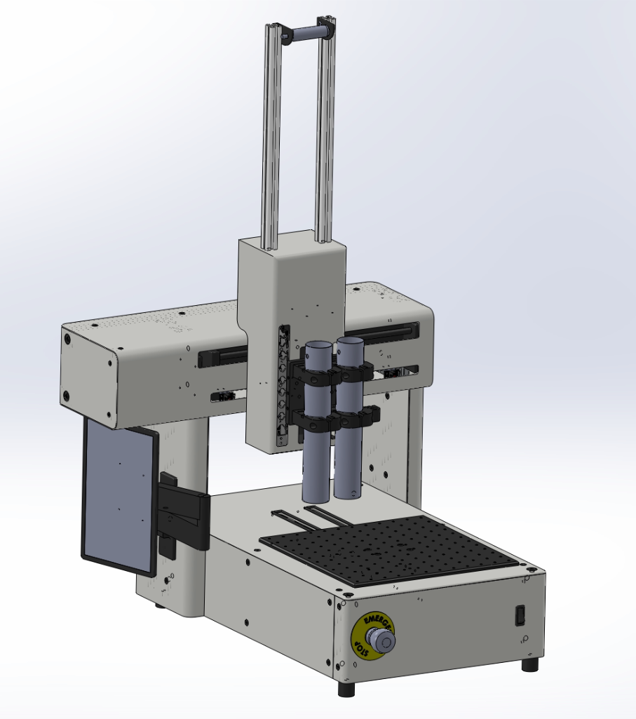
Full System with Dual CIJ printheads and 12"x12" Tooling Plate

M3800.png


Outcome

The system is currently in the prototype phase and is actively progressing through fabrication and assembly. Core design architecture, component selection, and system layout have been completed, with parts now being manufactured and integrated into the first physical build.

This stage is focused on validating mechanical fit, motion performance, marking accuracy, and overall system functionality under real-world conditions. Ongoing iteration is expected as components are tested and refined, with insights from the prototype build informing final design adjustments for future production-ready versions.