

Metal Tubing Beading Machine
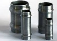
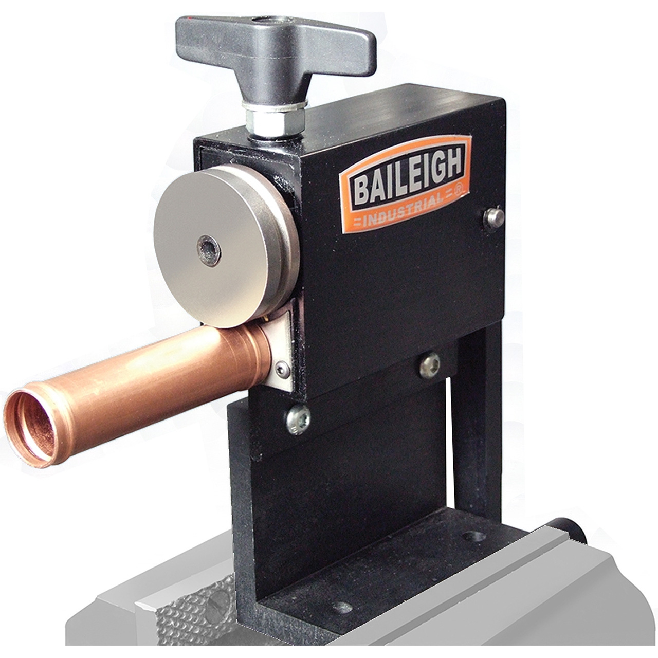
At the start of my internship, I was given a project by one of my managers to redesign and assemble a beading machine he had given up trying to fix nine months prior. A beading machine is used to create a portuding ring around metal tubes; examples of beaded tubes and a beading machine are shown below.
My manager had attempted to reverse engineer the design of an existing beading machine to create one that could bead a larger diameter tube. Once assembled, 0% of the parts yielded by the machine were within tolerance specifications: the beads were uneven and imprecise, with the tubing occasionally getting bent or cut. The machine was left to sit for nine months for the next intern to fix the following issues: misalignments, the bead head bearing block moved when pressure was applied, and both shafts were free-spinning. To solve the free-spinning shafts, I had the arbor die and bead arbor welded to their respective shafts. To fix the misalignment issues, I double-checked the tolerances on the adjustment block and the large gear bearing block (parts that had been machined in-house) against a CAD model of our functioning machine and found inconsistencies. I remade the parts on CAD with the proper dimensions and made a few design modifications, such as additional mounting holes, to improve alignment. Finally, to keep the bead head bearing block from moving when pressure was applied by turning the top knob, I replaced its spring with a stiffer and more robust one. After reassembling the machine with my newly modified, welded, and machined parts, it functioned smoothly as intended and yielded 100% of parts within the tolerance range. I was expected to make a small amount of progress on this project throughout my internship and let my manager complete it afterwards, but I had it fully functioning (to this day) in less than two weeks. Unfortunately, company policy prohibits me from sharing photos of anything on the production floor, so I can only show the internal components of the machine and some CAD model screenshots I had saved.
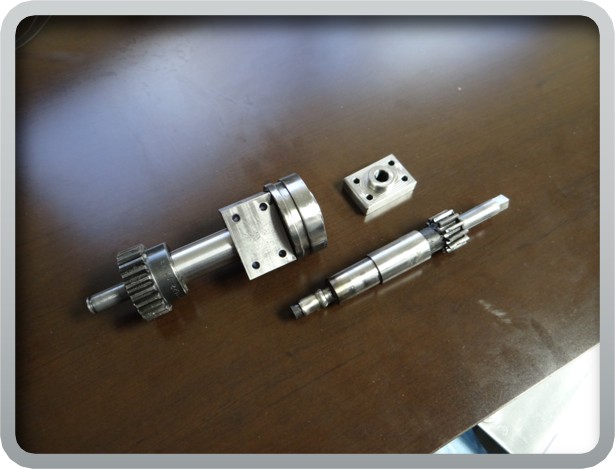
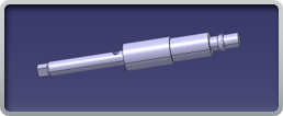

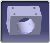
Pictured from left to right: Finished components, arbor die shaft, adjustment block, and large gear bearing block.
Torque Gun Holder
At the start of my internship, the plant I worked at purchased a $7000 torque gun to aid in the manufacturing process of a high-volume part. For a torque gun with a reaction arm (pictured below), the arm spins around the barrel until it is stopped, allowing the torque to be applied. Assembly associates were originally torquing down a large bolt on up to 150 parts per day with a standard manual torque wrench until the torque gun with a reaction arm was purchased. However, a few new problems arose since neither their workspaces nor part-holding fixtures had a structure in place to counteract the reaction arm, and associates found it difficult to hold the heavy torque gun in the exact needed position to ensure proper torque angle. To fix these issues, I designed a holding fixture for the torque gun that would bolt on to the slotted workbenches associates used when creating that specific part. It featured a slot for the base of the torque gun to slide into the exact position and angle necessary to ensure 100% precision of the torque angle applied, modular bolt holes to adjust position on the workbench if necessary, and an extruding arm for the reaction arm to stop rotation. I had our CNC machinist machine my part out of aluminum, and it worked exactly as intended in testing: torque angle precision was 100% and associates could now gently pull the trigger on the fully supported torque gun until torque was applied instead of holding its substantial weight up. Associates expressed their gratitude to me for making this repetitive process more ergonomic and safer by eliminating the strain on their shoulders they experienced by holding a heavy object at an awkward angle for so long. This was my favorite project at Collins Aerospace; seeing the reactions of people you helped and being praised as an intern felt very rewarding and drove me to make more process improvements at the company. Due to company policy, I am only able to share pictures of the CAD. Unfortunately, I no longer have access to these files, and the only screenshot I saved does not show the full part. At the reader's request, I can share a letter of recommendation from my manager emphasizing the success and positive impact of these projects.
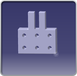
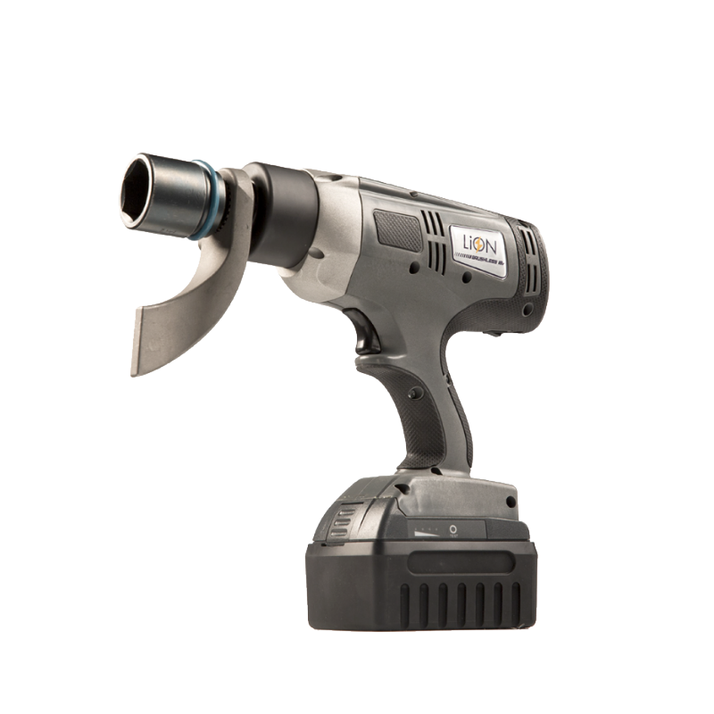
Torque gun holder block and example of a torque gun with a reaction arm.
Rivet Crimping Gun Stabilizer
Another high-volume part made at my facility required rivets to be crimped onto a thin metal plate. Assembly associates would use a crimping gun attached to a cylindrical hydraulic tank and a pedal to activate. When the pedal was pressed to crimp the part, the pressure released would knock over the hydraulic tank, which sat on the floor unevenly, and associates would have to reach down to set it upright and rearrange the hydraulic hoses for each part made. This was both time-consuming and unnecessarily strenuous on the back. I first designed a flat-bottomed cube base for the hydraulic tank to slide into and be bolted down out of scrap wood. After I tested that the design prevented the hydraulic tank from moving, I recreated my design in CAD and 3D printed the stabilizer base for a more proper and aesthetic solution than the functional scrap wood screwed together. I made the parts out of PETG with 100% infill, as the weight was an important factor in keeping the tank stable. The associates again expressed their gratitude to me for making their repetitive task much simpler and less strenuous. I then conducted a time study comparing the time to crimp 10 parts with and without the improvement and found a 167% increase in manufacturing time! Again, no pictures are available for this project, but it is still in use and praised by my manager and the associates who use it.