Custom Embedded Control Board (Schematic & PCB Design)
This project involved the complete electrical design of a custom embedded control board, from system-level power architecture down to schematic capture and PCB layout. The design integrates power regulation, motor/actuator driving, sensing, and microcontroller-based control into a single, manufacturable board.
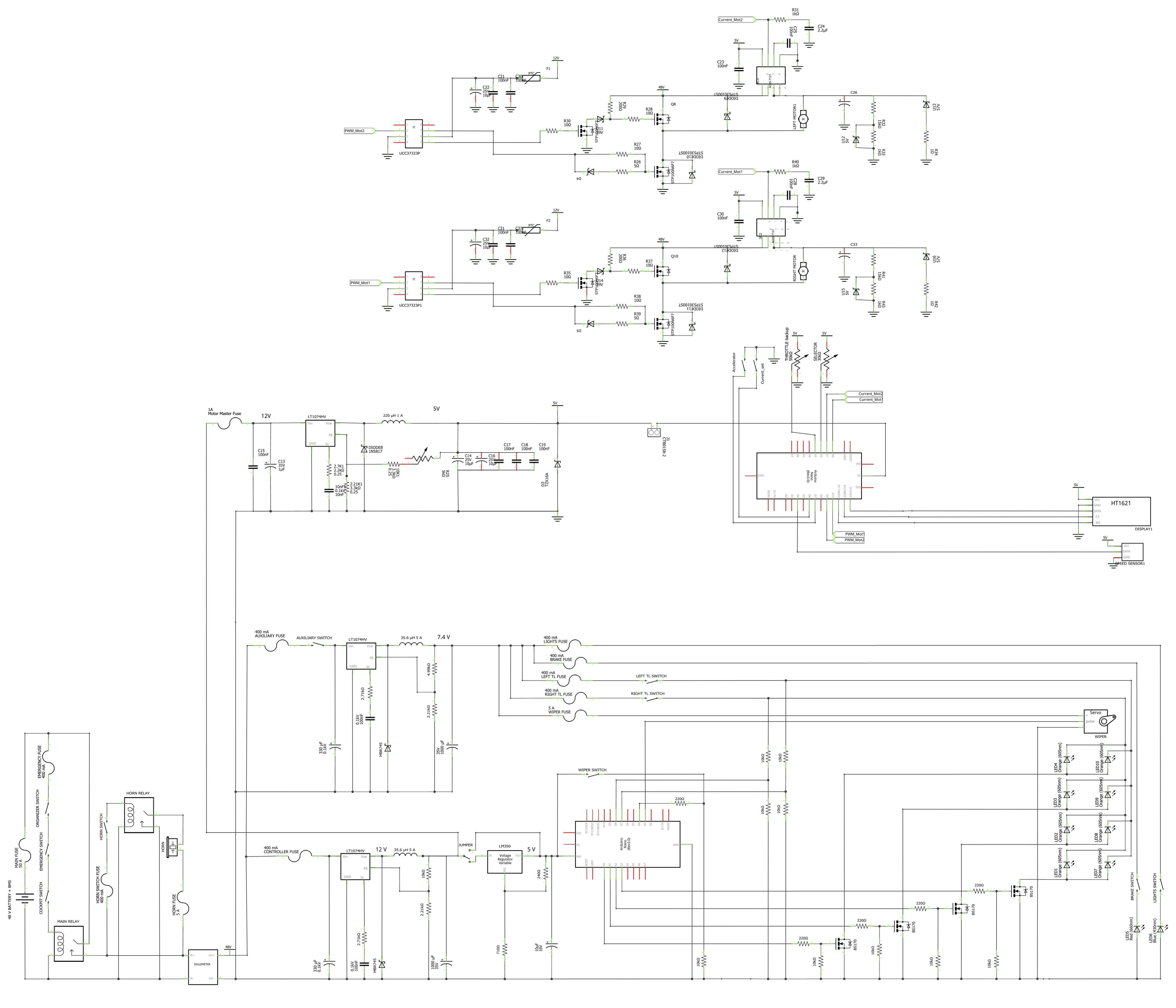
I developed the full schematic, defining power domains, signal conditioning, protection, and interfaces. The system includes multiple regulated rails (e.g., battery input, 12 V, 7.4 V, and 5 V), fuse-protected loads, and dedicated sections for motors/servos, auxiliary peripherals, and logic. Careful attention was given to grounding, decoupling, and current paths to ensure stable operation in a mixed-signal, high-current environment.
Key aspects of the design include:
Power Management: Battery input protection, fusing, DC-DC regulation, bulk and local decoupling, and rail distribution for logic and loads.
Actuator & Load Driving: Discrete transistor/MOSFET stages with flyback protection for inductive loads (motors, relays, servos).
Microcontroller Integration: Clean separation of digital I/O, PWM, ADC, and communication lines, with proper pull-ups, filtering, and reference routing.
Protection & Reliability: Automotive-style fuses, TVS/diode protection, current sensing points, and robust connector interfaces.
Modularity & Debuggability: Clearly partitioned schematic blocks, test points, and labeled nets to support bring-up and troubleshooting.
I then translated the schematic into a PCB layout, focusing on:
Proper placement of regulators and high-current paths to minimize voltage drop and EMI.
Short, low-impedance decoupling loops for sensitive ICs.
Clear separation between power, motor, and logic sections.
Manufacturable routing, consistent net classes, and connector accessibility.
This project demonstrates my ability to take a system from electrical requirements to a complete, production-ready schematic and PCB, with strong attention to power integrity, protection, and real-world deployment constraints.