


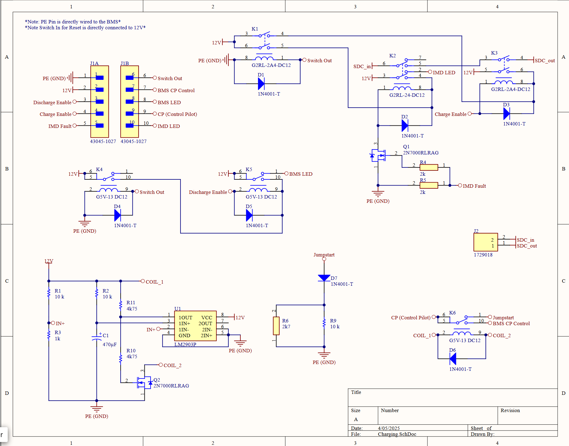
There are two main segments of the control system that had to be designed. One of them was to interface with the J1772 charging port. The goal was not to have auxiliary power on the charge cart. To start the handshake protocol, we hardwired resistors in the PCB to take care of that. By using a comparator, we implemented a time delay so the port could then directly interface with the battery management system.
The rest of the schematic is related to the shutdown circuit, incorporating a latching relay as our shutdown mechanism on the car.
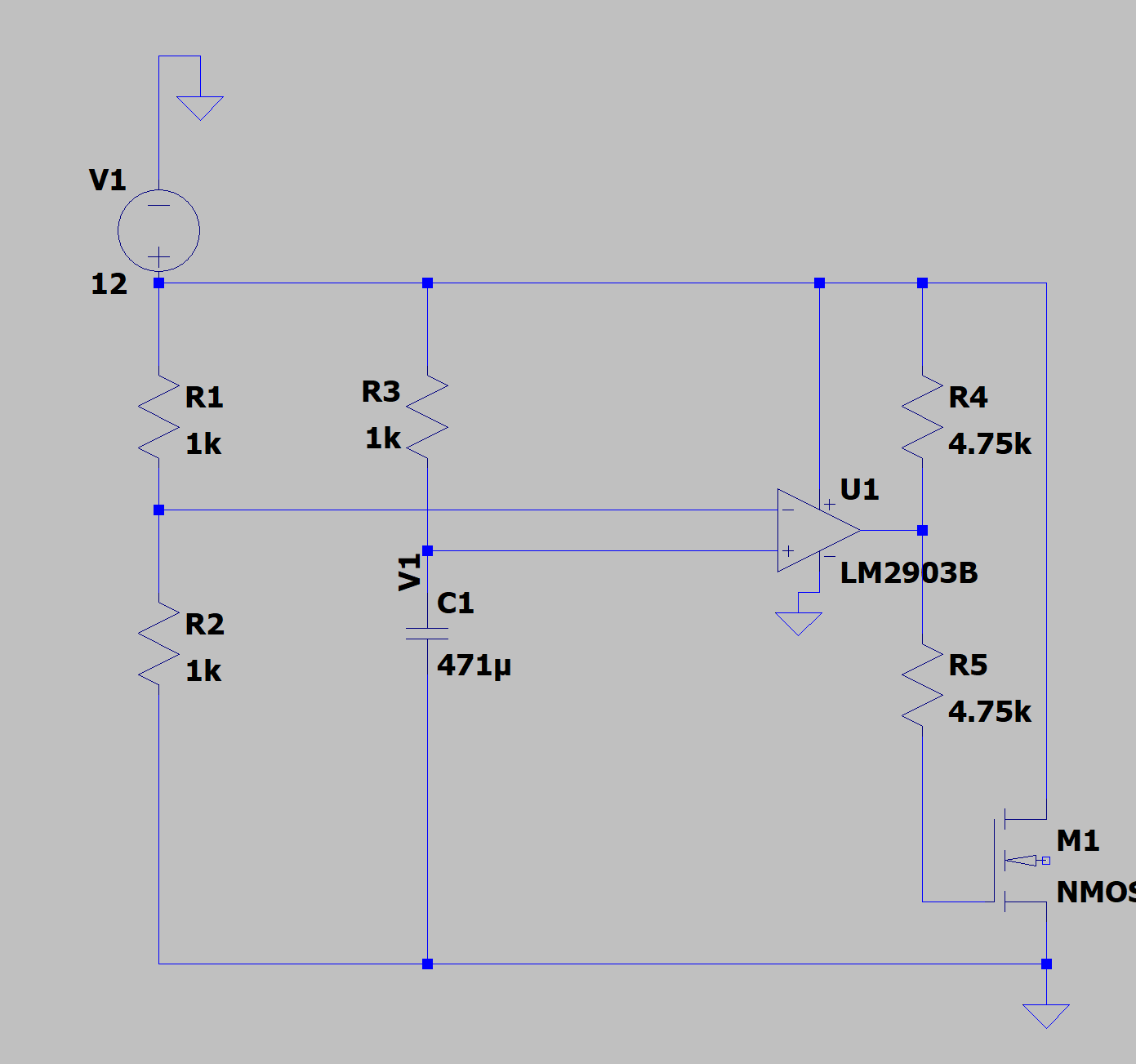
I utilized LTSpice to simulate the time delay using the specific comparator component we were working with, ensuring the desired behavior. This included importing the PSpice file and running a transient analysis from it.
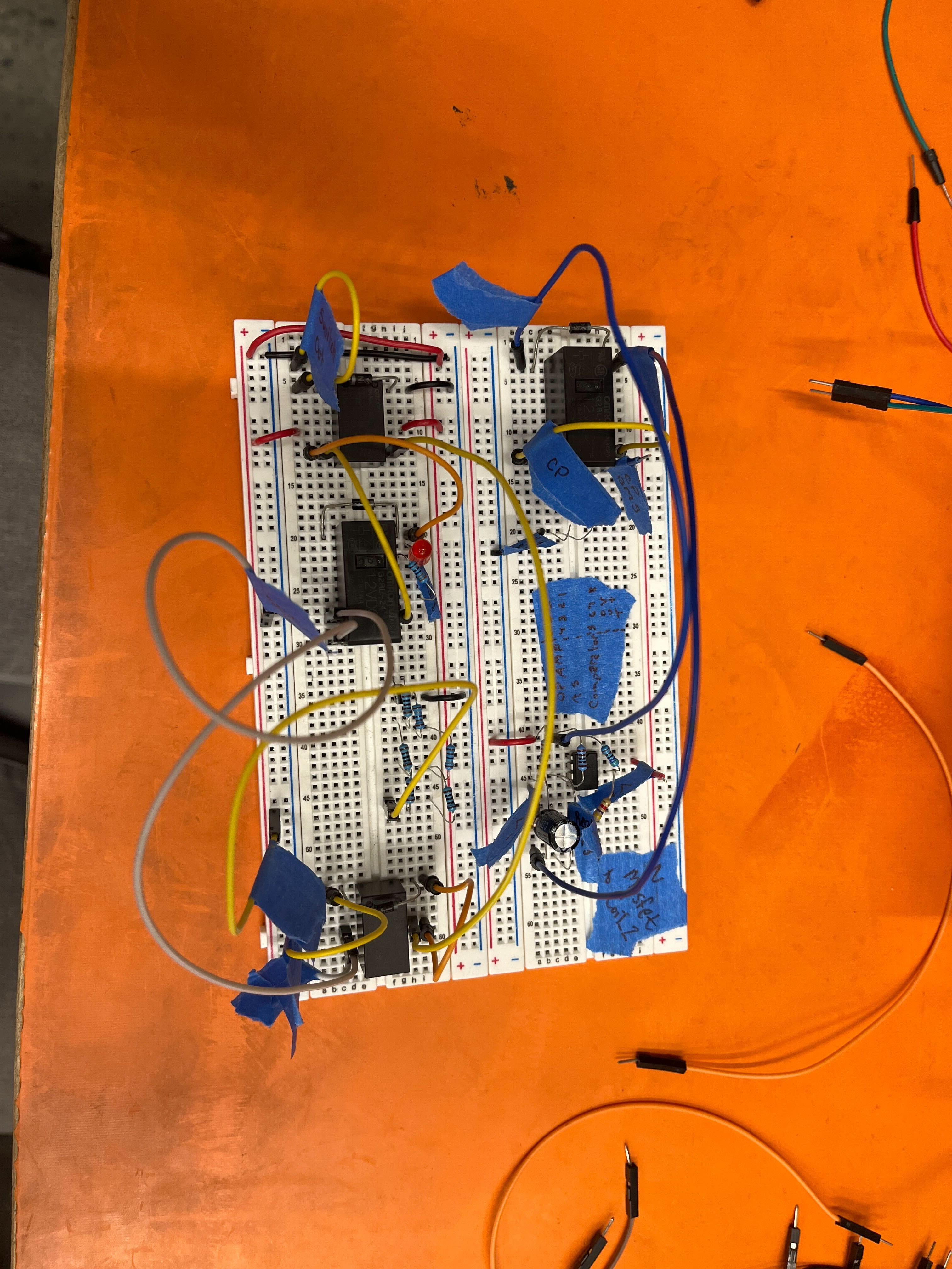
I tested the PCB using a test harness with dummy signals to test all the functions on the PCB. The first iterations had some issues, so I reworked the PCB to make the needed changes.
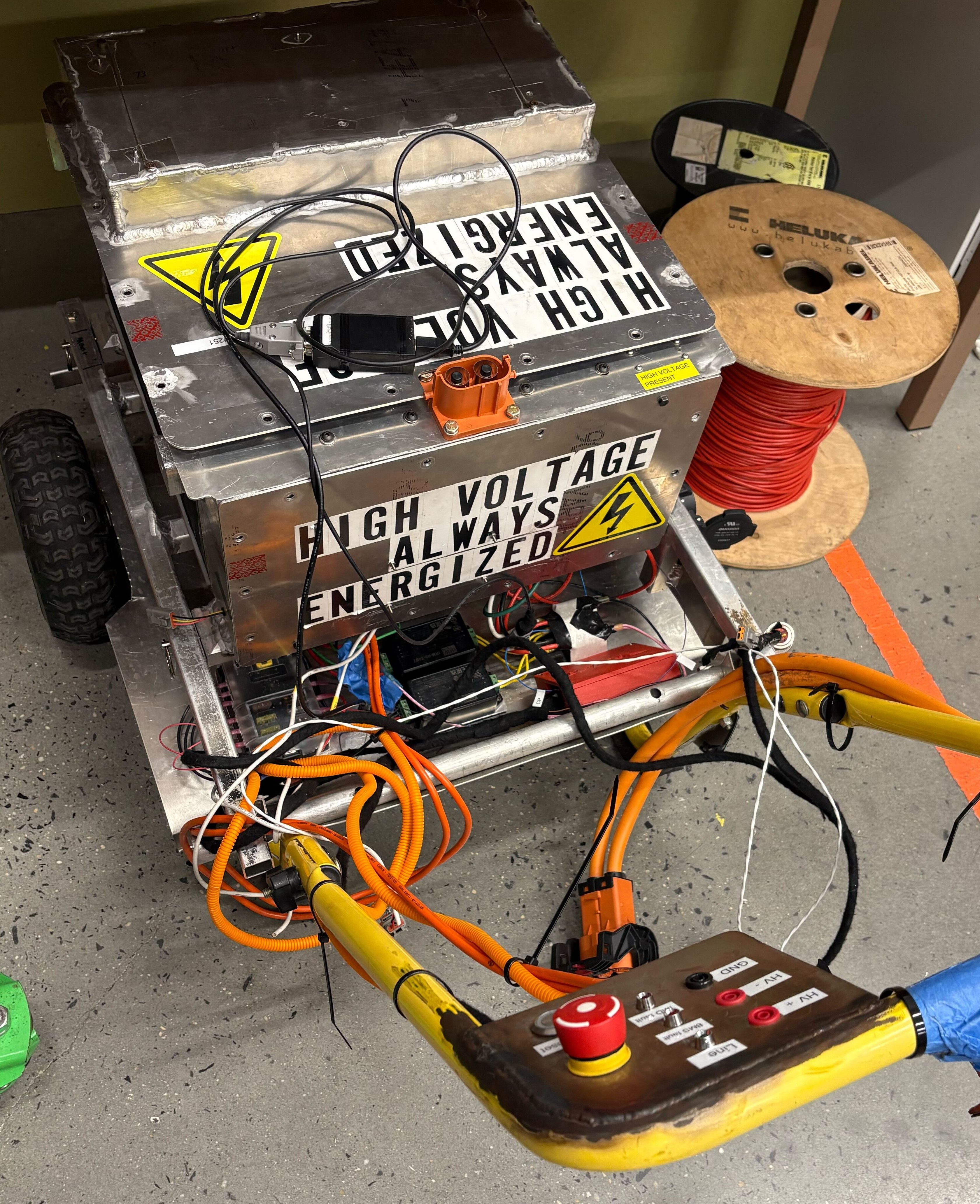
The PCB had to be integrated onto the charge cart and with the charger. I wired the shutdown circuit on the cart, relays, and the power supplies on the cart. I used various types of crimps and connectors. Some connections had to be soldered in the cart.