


Objective
The goal was to design a master-slave control system capable of amplifying user input force while maintaining real-time position tracking between two brushed DC motors. The system was intended to replicate the motion of the master unit through the slave motor with high precision and low latency.
System Design
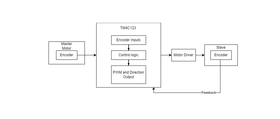
The control architecture relied on two TM4C123 microcontrollers — one for the master unit and one for the slave.
- Master side: Captured position via potentiometer and transmitted it digitally.
- Slave side: Received target position, compared it to local feedback, and applied a PD controller to drive the actuator.
Communication and debugging were performed through UART at 9600 baud, and PWM signals controlled motor speed and direction.
Control Strategy
A PD controller was implemented for accurate and stable motion replication:
- 𝐾𝑝 = 60, 𝐾𝑑 = 5
- Achieved quick response with minimal overshoot
- Excluded 𝐾𝑖 to avoid integrator wind-up and simplify tuning.
Implementation
The implementation involved:
- Hardware: TM4C123 LaunchPad, brushed DC motors, potentiometers, and H-bridge driver (TA7267BP).
- Software: Developed in TI Code Composer Studio using TivaWare library.
- Communication: UART used to display desired and actual positions for real-time validation.
Testing confirmed the system could replicate movements with high accuracy and maintain update rates above 10 Hz.
Challenges
- Tuning PD parameters for the right balance between stability and responsiveness.
- Managing electrical noise in potentiometer readings.
- Meeting real-time constraints with limited computational resources.
Results
- Successfully achieved real-time, low-latency performance.
- The slave motor followed master motion accurately with minimal lag.
- Demonstrated robustness and repeatability during final demo.
Future Improvements
- Incorporate wireless communication between units.
- Expand to multi-DOF robotic arms.
- Implement adaptive or model-based control for greater accuracy.
#include <stdint.h>
#include <stdbool.h>
#include <stdlib.h>
#include <string.h>
#include "hw_memmap.h"
#include "hw_types.h"
#include "hw_gpio.h"
#include "sysctl.h"
#include "gpio.h"
#include "pwm.h"
#include "pin_map.h"
#include "adc.h"
#include "uart.h"

// Define the PWM frequency
#define PWM_FREQUENCY 1000

// PID controller constants
#define KP 60.0  // Proportional gain
#define KI 0.0  // Integral gain
#define KD 5.0  // Derivative gain
int32_t constraintValue = 15000;

// Global variables for PID control
int32_t previousError = 0; // Previous error value for derivative calculation
int32_t integral = 0;      // Integral term for PID control

void UART0_Init(void) {
    SysCtlPeripheralEnable(SYSCTL_PERIPH_UART0);
    SysCtlPeripheralEnable(SYSCTL_PERIPH_GPIOA);

    GPIOPinConfigure(GPIO_PA0_U0RX);
    GPIOPinConfigure(GPIO_PA1_U0TX);
    GPIOPinTypeUART(GPIO_PORTA_BASE, GPIO_PIN_0 | GPIO_PIN_1);

    UARTConfigSetExpClk(UART0_BASE, SysCtlClockGet(), 115200,
                        (UART_CONFIG_WLEN_8 | UART_CONFIG_STOP_ONE |
                         UART_CONFIG_PAR_NONE));

    UARTEnable(UART0_BASE);
}

void UART0_SendString(const char *str) {
    while (*str) {
        UARTCharPut(UART0_BASE, *str++);
    }
}

void UART0_SendInt(int32_t value) {
    char buffer[12]; // Buffer to hold the string representation of the integer
    itoa(value, buffer, 10); // Convert integer to string
    UART0_SendString(buffer); // Send the string via UART
}

void itoa(int value, char* buffer, int base) {
    char *ptr = buffer, *ptr1 = buffer, tmp_char;
    int tmp_value;

    if (base < 2 || base > 36) { *buffer = '\0'; return; }

    do {
        tmp_value = value;
        value /= base;
        *ptr++ = "zyxwvutsrqponmlkjihgfedcba9876543210123456789abcdefghijklmnopqrstuvwxyz"[35 +
(tmp_value - value * base)];
    } while ( value );

    // Apply negative sign
    if (tmp_value < 0) *ptr++ = '-';
    *ptr-- = '\0';
    while (ptr1 < ptr) {
        tmp_char = *ptr;
        *ptr-- = *ptr1;
        *ptr1++ = tmp_char;
    }
}

// Function to initialize system clock, GPIO, PWM, and ADC
void setup() {
    // Set the system clock to 50 MHz
    SysCtlClockSet(SYSCTL_SYSDIV_4 | SYSCTL_USE_PLL | SYSCTL_OSC_MAIN | SYSCTL_XTAL_16MHZ);

    UART0_Init();
    UART0_SendString("UART Initialized.\r\n");

    // Enable peripherals for GPIO, PWM, and ADC
    SysCtlPeripheralEnable(SYSCTL_PERIPH_GPIOA); // Enable GPIO Port A
    SysCtlPeripheralEnable(SYSCTL_PERIPH_GPIOB); // Enable GPIO Port B
    SysCtlPeripheralEnable(SYSCTL_PERIPH_GPIOE); // Enable GPIO Port E
    SysCtlPeripheralEnable(SYSCTL_PERIPH_GPIOF); // Enable GPIO Port F
    SysCtlPeripheralEnable(SYSCTL_PERIPH_PWM1);  // Enable PWM1 module
    SysCtlPeripheralEnable(SYSCTL_PERIPH_ADC0);  // Enable ADC0 module

    // Wait for peripherals to be ready
    while(!SysCtlPeripheralReady(SYSCTL_PERIPH_GPIOA)); // Wait for GPIO Port A to be ready
    while(!SysCtlPeripheralReady(SYSCTL_PERIPH_GPIOB)); // Wait for GPIO Port B to be ready
    while(!SysCtlPeripheralReady(SYSCTL_PERIPH_GPIOE)); // Wait for GPIO Port E to be ready
    while(!SysCtlPeripheralReady(SYSCTL_PERIPH_GPIOF)); // Wait for GPIO Port F to be ready
    while(!SysCtlPeripheralReady(SYSCTL_PERIPH_PWM1));  // Wait for PWM1 module to be ready
    while(!SysCtlPeripheralReady(SYSCTL_PERIPH_ADC0));  // Wait for ADC0 module to be ready

    UART0_SendString("Peripherals Enabled.\r\n");

    // Unlock PF0 and PF4 for switch usage
    HWREG(GPIO_PORTF_BASE + GPIO_O_LOCK) = GPIO_LOCK_KEY;
    HWREG(GPIO_PORTF_BASE + GPIO_O_CR) |= GPIO_PIN_0 | GPIO_PIN_4;
    HWREG(GPIO_PORTF_BASE + GPIO_O_LOCK) = 0;

    // Configure GPIO for switch (PF4) and magnet control (PB2)
    GPIOPinTypeGPIOInput(GPIO_PORTF_BASE, GPIO_PIN_4); // Configure PF4 as input (switch)
    GPIOPadConfigSet(GPIO_PORTF_BASE, GPIO_PIN_4, GPIO_STRENGTH_2MA,
GPIO_PIN_TYPE_STD_WPU); // Enable weak pull-up resistor on PF4
    GPIOPinTypeGPIOOutput(GPIO_PORTB_BASE, GPIO_PIN_2); // Configure PB2 as output (magnet
control)

    // Initialize PB2 to low
    GPIOPinWrite(GPIO_PORTB_BASE, GPIO_PIN_2, 0);

    // Configure PWM
    GPIOPinTypePWM(GPIO_PORTE_BASE, GPIO_PIN_4 | GPIO_PIN_5); // Configure PE4 and PE5 as
PWM output
GPIOPinConfigure(GPIO_PE4_M1PWM2); // Map PE4 to M1PWM2
    GPIOPinConfigure(GPIO_PE5_M1PWM3); // Map PE5 to M1PWM3
    PWMGenConfigure(PWM1_BASE, PWM_GEN_1, PWM_GEN_MODE_DOWN |
PWM_GEN_MODE_NO_SYNC); // Configure PWM generator 1
    uint32_t pwmPeriod = SysCtlClockGet() / PWM_FREQUENCY;
    PWMGenPeriodSet(PWM1_BASE, PWM_GEN_1, pwmPeriod); // Set PWM period based on system
clock
    PWMPulseWidthSet(PWM1_BASE, PWM_OUT_2, 0); // Initialize PWM pulse width for PE4 to 0
    PWMPulseWidthSet(PWM1_BASE, PWM_OUT_3, 0); // Initialize PWM pulse width for PE5 to 0
    PWMOutputState(PWM1_BASE, PWM_OUT_2_BIT | PWM_OUT_3_BIT, true); // Enable PWM
output on PE4 and PE5
    PWMGenEnable(PWM1_BASE, PWM_GEN_1); // Enable PWM generator 1

    UART0_SendString("PWM Initialized.\r\n");

    // Configure GPIO for motor direction
    GPIOPinTypeGPIOOutput(GPIO_PORTA_BASE, GPIO_PIN_2 | GPIO_PIN_3); // Configure PA2 and
PA3 as output

    // Configure ADC for master potentiometer (PE3) and slave potentiometer (PE2)
    ADCSequenceConfigure(ADC0_BASE, 3, ADC_TRIGGER_PROCESSOR, 0); // Configure ADC sequence 3
    ADCSequenceStepConfigure(ADC0_BASE, 3, 0, ADC_CTL_CH0 | ADC_CTL_IE | ADC_CTL_END); //
Configure ADC steps for master potentiometer
    ADCSequenceEnable(ADC0_BASE, 3); // Enable ADC sequence 3
    ADCIntClear(ADC0_BASE, 3); // Clear ADC interrupt flag for sequence 3

    ADCSequenceConfigure(ADC0_BASE, 2, ADC_TRIGGER_PROCESSOR, 0); // Configure ADC sequence 2
    ADCSequenceStepConfigure(ADC0_BASE, 2, 0, ADC_CTL_CH1 | ADC_CTL_IE | ADC_CTL_END); //
Configure ADC steps for slave potentiometer
    ADCSequenceEnable(ADC0_BASE, 2); // Enable ADC sequence 2
    ADCIntClear(ADC0_BASE, 2); // Clear ADC interrupt flag for sequence 2

    UART0_SendString("ADC Initialized.\r\n");
}

// Function to read ADC value from a given sequence
uint32_t readADC(uint32_t base, uint32_t sequence) {
    ADCProcessorTrigger(base, sequence); // Trigger ADC conversion
    while(!ADCIntStatus(base, sequence, false)); // Wait for ADC conversion to complete
    uint32_t value; // Variable to store ADC result
    ADCSequenceDataGet(base, sequence, &value); // Retrieve ADC result
    ADCIntClear(base, sequence); // Clear ADC interrupt flag
    return value; // Return ADC result
}

// PID control function
int32_t pidControl(int32_t setpoint, int32_t measuredValue) {
    int32_t error = setpoint - measuredValue; // Calculate the error
    integral += error; // Update integral term
 int32_t derivative = error - previousError; // Calculate derivative term
    previousError = error; // Update previous error
    int32_t output = (int32_t)(KP * error + KI * integral + KD * derivative); // Calculate PID output
    if (output >= constraintValue)
           {
               output = constraintValue;
           }else if (output <=-constraintValue)
           {
               output =-constraintValue;
           }
    return output; // Return PID output
}

void handleSwitchAndMagnet() {
    static bool magnetState = false; // Initial state of the magnet (off)
    static bool previousSwitchState = true; // Initial state of the switch (not pressed)

    // Read current switch state
    bool currentSwitchState = GPIOPinRead(GPIO_PORTF_BASE, GPIO_PIN_4) == 0;

    // Toggle magnet state when switch is pressed
    if (currentSwitchState && !previousSwitchState) {
        magnetState = !magnetState;
        GPIOPinWrite(GPIO_PORTB_BASE, GPIO_PIN_2, magnetState ? GPIO_PIN_2 : 0);
    }

    // Update previous switch state
    previousSwitchState = currentSwitchState;
}

int main() {
    setup(); // Call setup function to initialize hardware

    uint32_t pwmPeriod = SysCtlClockGet() / PWM_FREQUENCY;

    while (1) { // Main loop
        // Read desired position from master potentiometer (PE3)
        int32_t desiredPosition = readADC(ADC0_BASE, 3)+260;
        //UART0_SendString("Desired Position: ");
        //UART0_SendInt(desiredPosition); // Send desired position value
        //UART0_SendString("\r\n");

        // Read actual position from slave potentiometer (PE2)
        int32_t actualPosition = readADC(ADC0_BASE, 2);
        //UART0_SendString("Actual Position: ");
        //UART0_SendInt(actualPosition); // Send actual position value
        //UART0_SendString("\r\n");

        // Calculate control signal using PID control
        int32_t controlSignal = pidControl(desiredPosition, actualPosition);
        //UART0_SendString("Control Signal: ");
        //UART0_SendInt(controlSignal); // Send control signal value
        //UART0_SendString("\r\n");

        // Set motor direction and PWM signals based on control signal
        if (controlSignal > 0) {
            GPIOPinWrite(GPIO_PORTA_BASE, GPIO_PIN_2, GPIO_PIN_2); // Set direction forward
            GPIOPinWrite(GPIO_PORTA_BASE, GPIO_PIN_3, 0); // Clear reverse direction pin
            PWMPulseWidthSet(PWM1_BASE, PWM_OUT_2, 50000 - abs(controlSignal)); // Set PWM duty
cycle for forward direction
            PWMPulseWidthSet(PWM1_BASE, PWM_OUT_3, 0); // Clear PWM duty cycle for reverse
direction
        } else {
            GPIOPinWrite(GPIO_PORTA_BASE, GPIO_PIN_2, 0); // Clear forward direction pin
            GPIOPinWrite(GPIO_PORTA_BASE, GPIO_PIN_3, GPIO_PIN_3); // Set direction reverse
            PWMPulseWidthSet(PWM1_BASE, PWM_OUT_2, 0); // Clear PWM duty cycle for forward
direction
            PWMPulseWidthSet(PWM1_BASE, PWM_OUT_3, 50000 - abs(controlSignal)); // Set PWM duty
cycle for reverse direction
        }

        handleSwitchAndMagnet(); // Handle switch and magnet control

        // Send debug information via UART
        UART0_SendString("Master Position: ");
        UART0_SendInt(desiredPosition);
        UART0_SendString(", Slave Position: ");
        UART0_SendInt(actualPosition);
        UART0_SendString(", Control Signal: ");
        UART0_SendInt(controlSignal);
        UART0_SendString("\r\n");
        //UART0_SendString(", Magnet State: ");


    }
}