


SPINCOATER
Any process that requires spreading a liquid over a wafer is done through a spin coater. Substrate thickness can be easily adjusted by varying the RPM the coater spins at.
Design
Our Club's proctoring professor had many gripes with existing spin coater designs. In Particular, the vacuum mechanism that typically holds the chuck in place was prone to failure when liquids sneak between the seal and chip, as pictured below.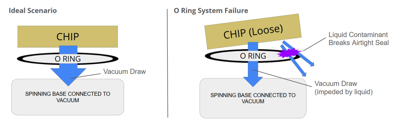
I knew I wanted to use some sort of chuck design in order to grab the chip by its sides. Typically this is not done in industry as the surface tension of liquids tends to pool around the teeth of any chuck. In industry this can lead to substrate variation, but it should be fine for our applications.
The bigger problem was that most chuck designs are very heavy or require extra tools in order to tighten them. I did some research and found a design called the "Longworth chuck", common in wood turning applications. This design is self tightening, so as the motor speeds up, the jaws grip tighter on the chip.
Through some online CAD files and drawings, I managed to reverse engineer the design.
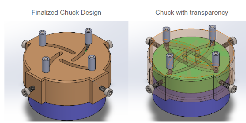
I used screws wrapped in heat shrink for the jaws with additional set screws to tighten the mechanism if needed. The tolerances in the design took a few iterations to iron out on my 3D printer, but I got it after ~3 iterations. The rest of the build was creating a stand for the chuck and a dish to collect excess liquid.

Build
This build was quite easy since everything was 3D printed. I used an XY-160D to drive a generic brushed motor I bought on amazon. This was controlled by an Arduino nano that ran a script which ramps the motor from 0-4000 RPM over a 30 second time interval, then holds at 4000RPM before spinning down.
In the future, I would like to get the chuck milled from solid aluminum. Since the hole on the bottom is not perfectly concentric with the shaft, the entire device has a tendency to vibrate off tables. Additionally, the whole vice would close significantly smoother if I could tighten up some of the tolerances. For now, this works quite well for our club, so realistically these are long term future changes.
LITHOGRAPHY
Lithography was always going to be our hardest challenge. Professional tools struggle at getting this right and DIY tools are going to be even worse. We knew that the HackerFab community was getting results by using a microscope and DLP projector, so we figured we should try using a microscope to run a test exposure.
Our Current Setup
This is what is currently used for test exposures.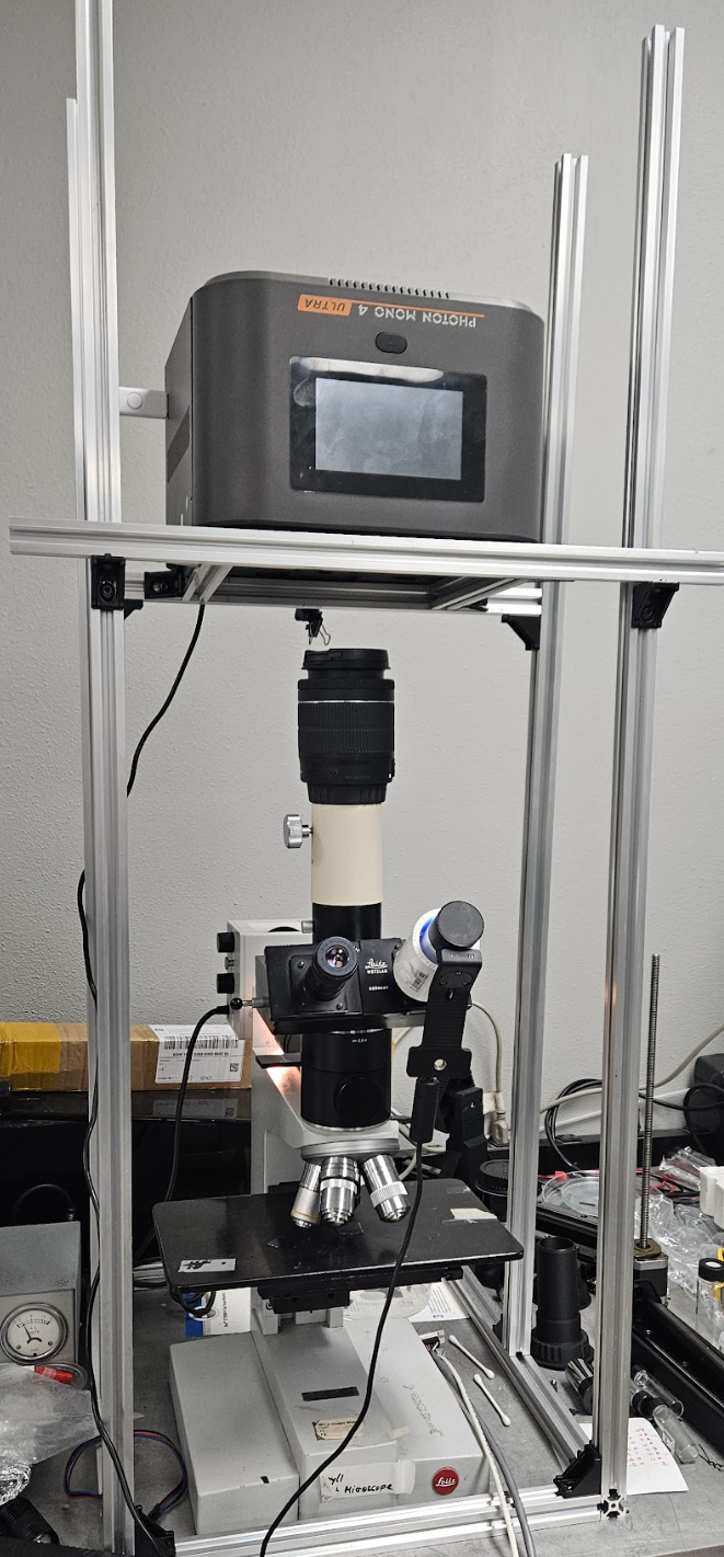
The basic setup is an upside down SLA 3D printer with a removed Z stage. This is what is used for our "mask" and light engine. The output of this printer is than run into a 54mm Canon lens. This lens allows us to perform some additional magnification and allows us to tweak magnification without uploading a separate slice profile to the printer. The Canon lens outputs into our microscope, which eventually outputs to our chip. A webcam is additionally mounted to the eyepiece in order to focus the printer output during light emission.
Current efforts are focused on removing the microscope from the optics stackup completely for the following reasons.
This is what the internals of the microscope looks like (Source: https://www.microscopyu.com/)

As you can see, there are actually two beam splitters in this microscope, one for the Epi Illuminator and one for the Trinocular. These beam splitters each eat 50% of our light, so only 25% of our UV intensity actually makes it to the objective. This is even a best case scenario as there is definitely refractive loss from the Canon lens and Objective lens.
Current efforts are focused on creating a "deconstructed" version of this microscope that has only one removable beam splitter. With this upgrade, we can still view the chip when necessary, but remove the beam splitter during exposures for maximum light output.