


Electric Go-Kart V1

BACKGROUND AND PROJECT OVERVIEW
Back in high school, I had a friend who built a go-kart with a Harbor Freight engine and a frame he found online. He invited me and a few others to come over and drive this contraption, the problem was it had no brakes. In typical teenager fashion, we drove it anyway. After a terrifying night of driving, I offered to mount some. During this process, I couldn't help but imagine how the system could be improved if it was electric.
This idea stuck with me going into college, I knew I had the skills to do it, the problem was money and time. I couldn't stop thinking about how fun it would be to have instant torque available to accelerate. Sometime during the year, I decided to start the CAD and see where it takes me, with plans to start the build over the summer.
GOALS
In short, Build a go-kart capable driving on standard road conditions using electric motors.
| Requirements | Constraints | |
| Top speed must meet or exceed 30mph |
Construction must be achievable with hobbyist tools | |
| Range must meet or exceed 15 miles | Lithium-Ion Batteries must be used for reliability, range, and power density | |
| Kart must have capacity for future upgrades | BLDC Hub Motors will be used to achieve top speed and allow for all wheel drive | |
| Frame must be custom and constructed from scratch |
Online liquidation websites and Ebay will be used to source components | |
| Kart must be safe enough to drive consistently for all requirements |
Kart will have effective brakes, seatbelts, and emergency protocols for electrical subsystems | |
| Costs may not exceed $3000 | Suspension system mandatory | |
| Electric power train must be used |
||
| Kart must be comfortable to drive | ||
In addition to these requirements and constraints, whatever is designed must be fun to drive and teach practical skills.
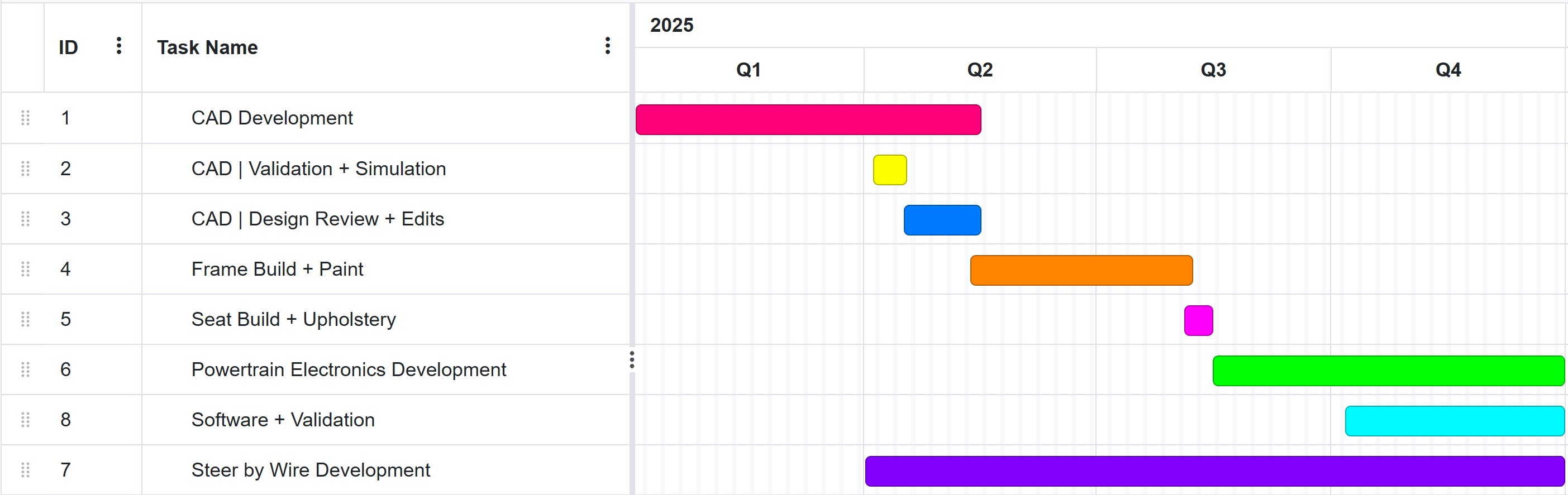
SCHEDULING
CAD
Initial Designs/Considerations
Firstly, I had to figure out how to CAD a frame in SOLIDWORKS. Ideally, my solution would have to be easy to edit in the future. I had done lots of assembly CAD before, so initial steps were simply creating lengths of tube as a part and saving multiple configurations of the tube. This gets EXTREMELY tedious when you have lots of structural members.
As such, I did some research and found a tool called weldments. This allows you to create a 3D Sketch of a frame and select lengths of a sketch to become bars. After a few YouTube videos, I got the hang of it. Joint order specification was something that was something I initially struggled with, but it eventually became intuitive.
Initial experimentation and Design
This figure shows the initial experimentation I conducted with learning weldments.
I measured my dimensions seated (shown by the construction lines), that way I could figure out how big I wanted to make the frame.
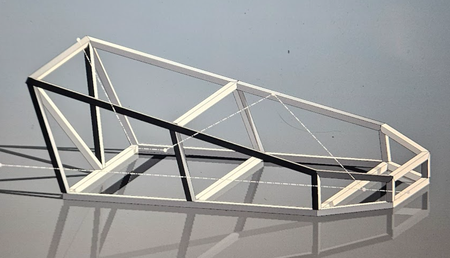
After some more effort, I landed on this design

There were a few immediate design complications. Firstly, the E-scooter motors I had selected have a shaft that must be attained from both sides. Secondly, Suspension for such a system was going to be a nightmare. I did some research on go kart suspension and found a post from a build by "Squidbonez" on the DIY Go Karts Forum. He uses what I have dubbed "Mid Frame Suspension", where the frame is jointed where the weight rests. This design is very simple and presumably quite effective.
My Design vs Inspiration Build
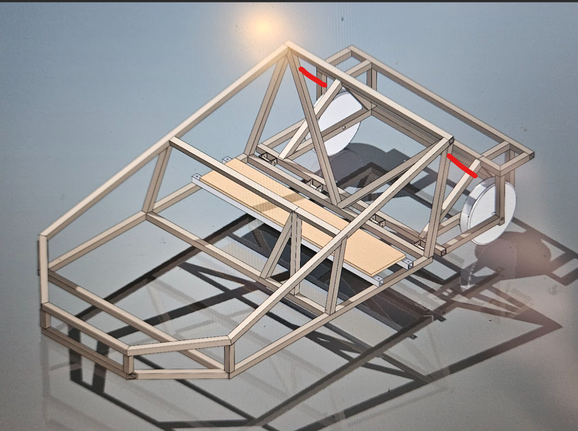
Here, the red lines indicate future suspension members between the for and aft frames.
During a design review with an engineer, he told me that while this might help with bumps, I would need a bespoke solution for the front wheels, since this design would be only semi-effective with large off road wheels, something I would not have. After this review, I decided to implement a double wishbone front suspension in addition to the mid frame suspension.
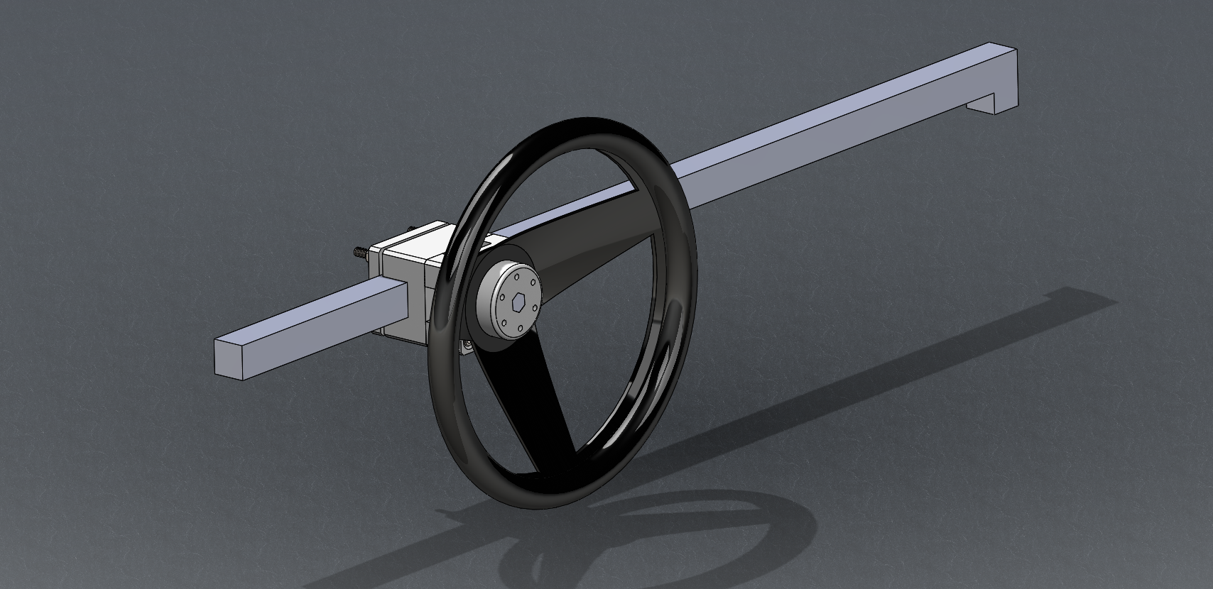
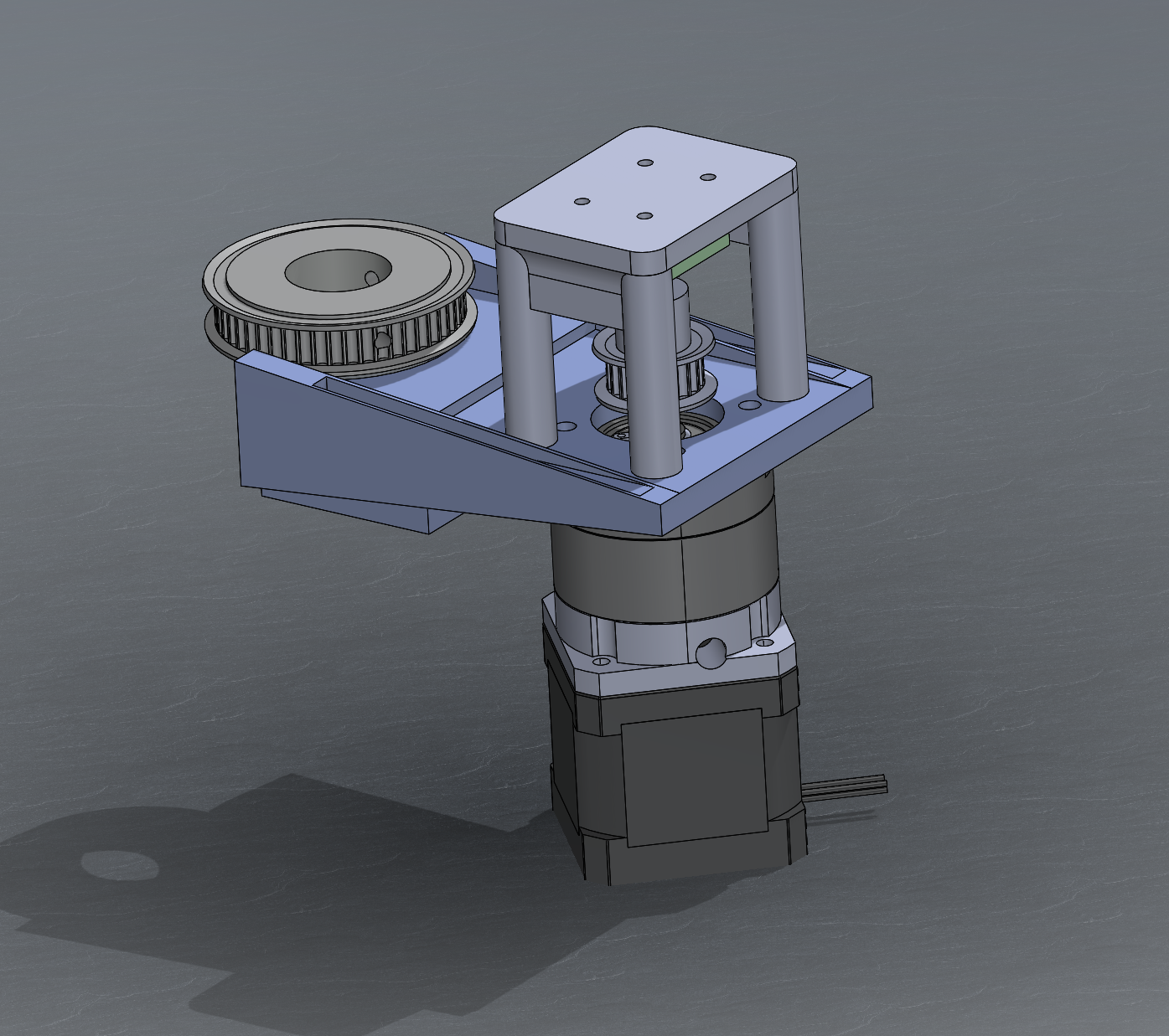
Next thing to tackle was the steering. I managed to get a steering rack from a 2005 Hyundai Sonata for $12 from an amazon liquidation website, so that was going to constrain the front wheels. The question is how to drive those front wheels. I settled on a steer by wire system, since I could possibly do some fun self driving stuff in the future with this system.
The system is two modules. A stepper motor with planetary gearbox is mounted to the steering rack, while a wheel with a potentiometer is mounted to the dash. Brackets for all of these components are custom and 3D printed. This setup is still largely unfinished and untested.
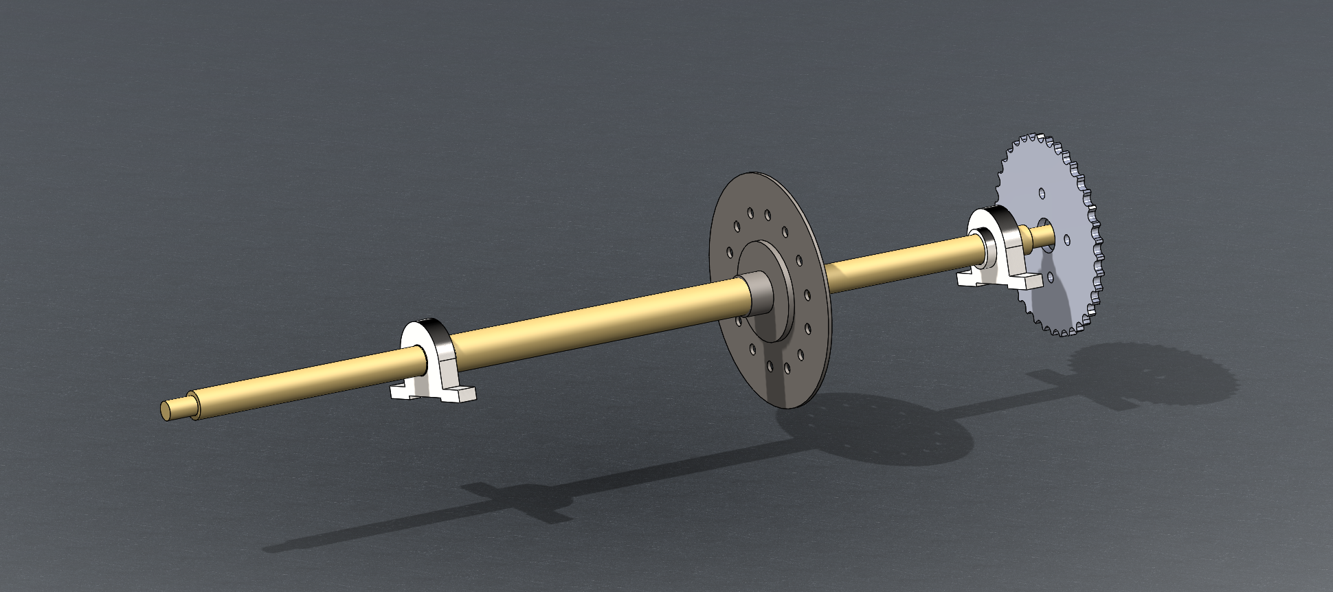
For brakes, I am using a generic amazon brake kit connected to the rear driver side wheel. The Kart should be small enough that braking one wheel is sufficient, but another brake can be added to the rear passenger wheel if needed. After purchasing this kit, I modeled it in solid works to check interferences.
I ended up modifying the mounting positions of the brakes and rotor sprocket to fit my specifications.

"Finalized" CAD
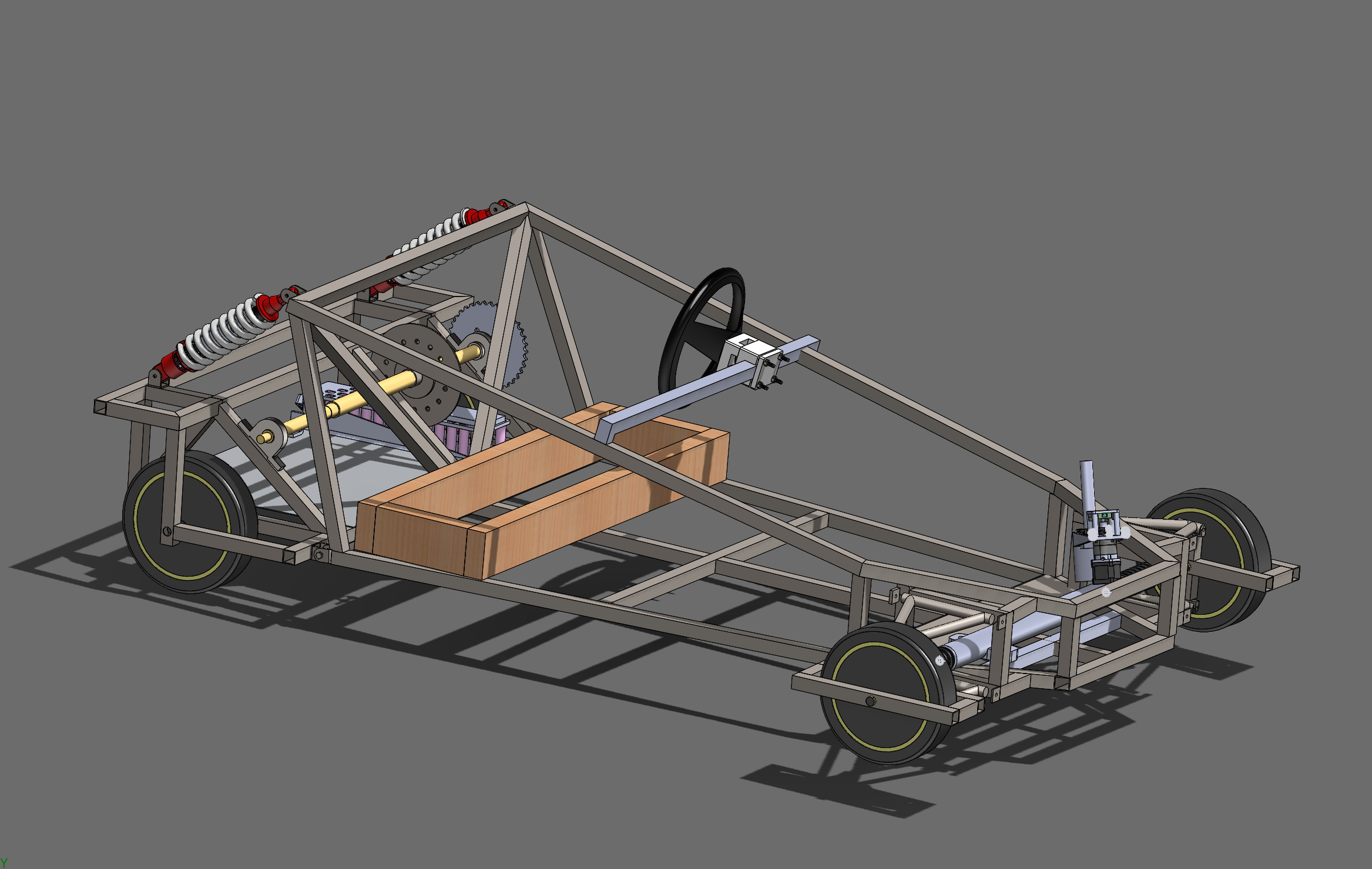
FRAME
With CAD Concluded, it was time to move on to the build. First thing on the docket was the frame. I went to my local metal supply company and bought 100' of 16 gauge steel.
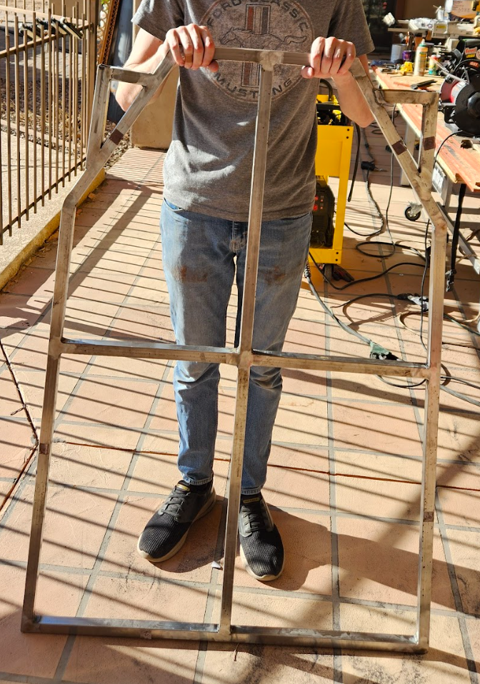
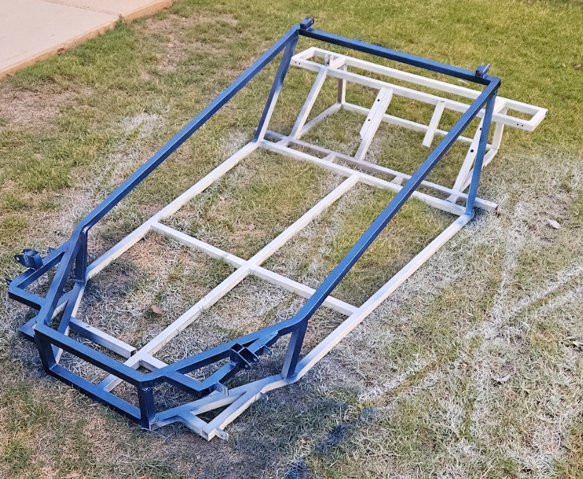
I started by welding the bottom of the frame since the superstructure would likely be more complicated. The superstructure required bending two long for/aft lengths and properly aligning them with the front "grill" which I knew would be problematic. The precision turned out to be much easier to achieve on a metal bender than I thought, and the front frame came out almost perfect.
Getting the angle measurements correct on the two rear bars supporting the superstructure was far more difficult. They were not aligned with any plane, so it took many cycles of tack > check alignment > grind > tack. I eventually got things symmetrical through this process.
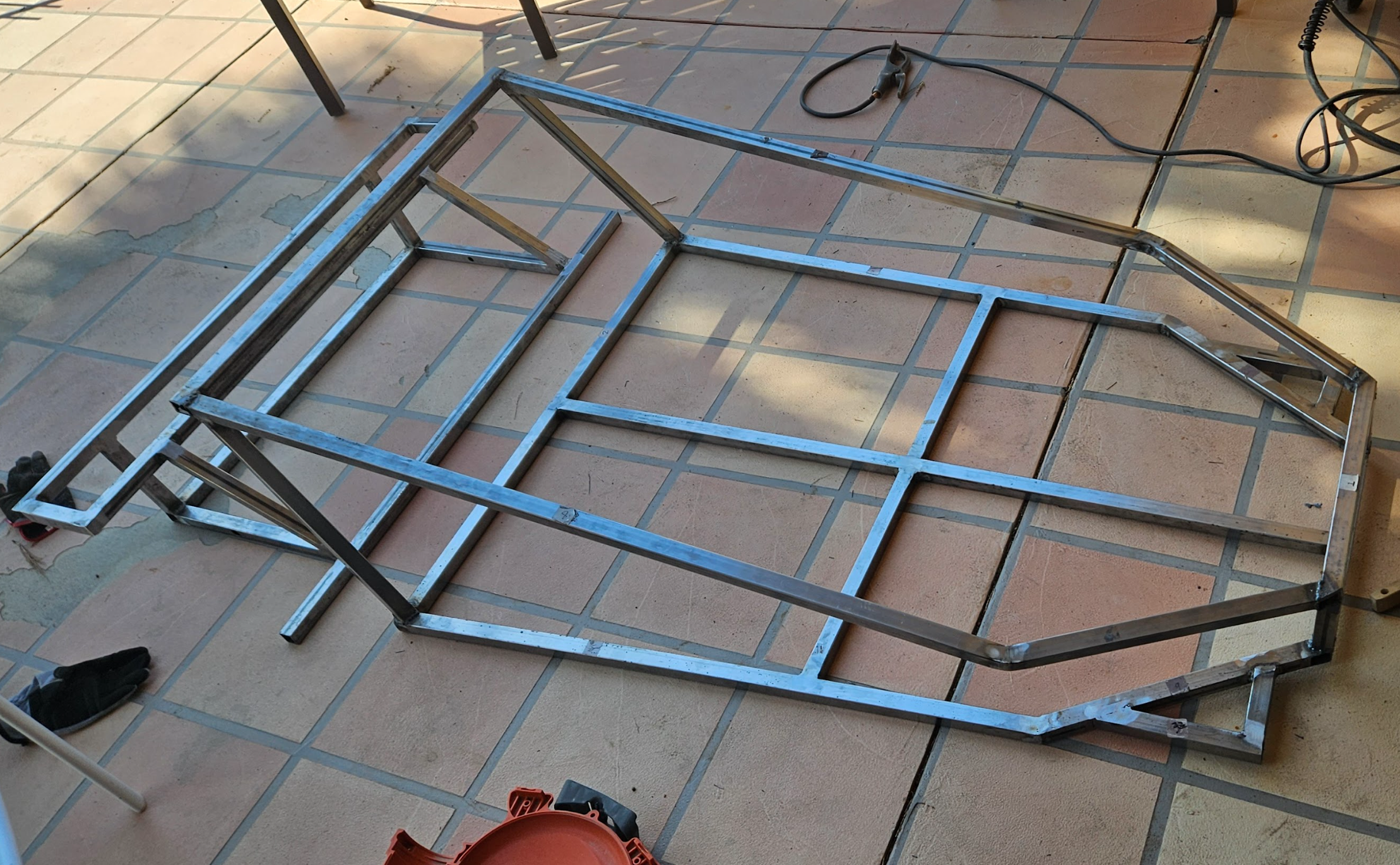
The rear frame was a piece of cake in comparison to the front. Everything was boxy and blocks could be used to align members before welding.
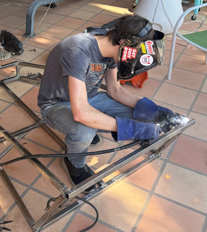
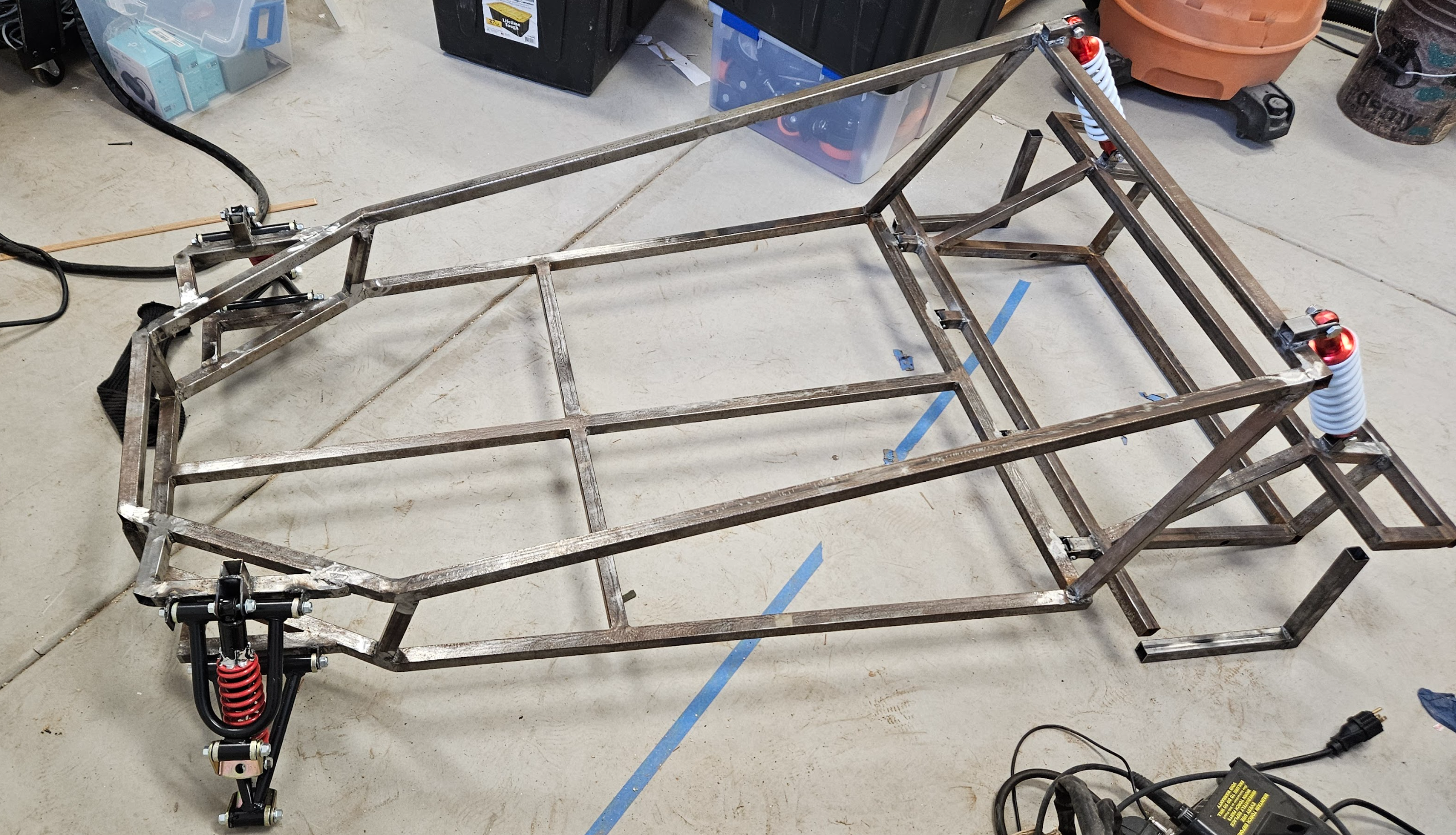
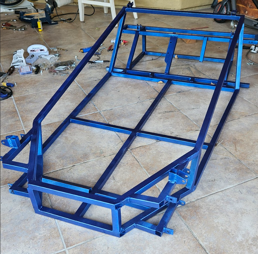
Frame Build
Paint
The painting process took a surprising amount of time. Without access to professional equipment, I was pretty much forced to use spray paint. Additionally, not having a sand blaster forced me to blow through 3 or 4 wire brushes on my angle grinder while prepping the surface. Not the end of the world, but certainly expensive.
I opted paint with 2 coats of primer, 3 coats of color, and 2 coats of gloss clear coat. This is enough to protect the surface from rust and light scrapes, but it still easily chips and I frequently have to touch up certain spots. For color, I opted for a metallic blue, which looks like a real car.
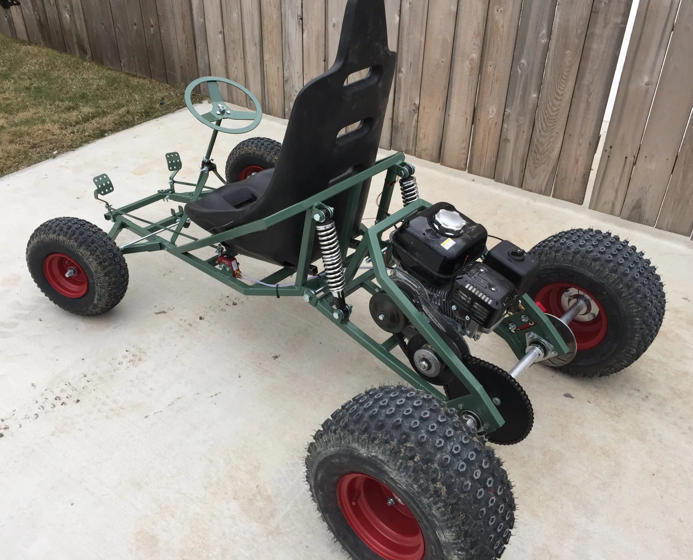
With paint, It was time to call the main frame complete and mount suspension, motors, and brakes
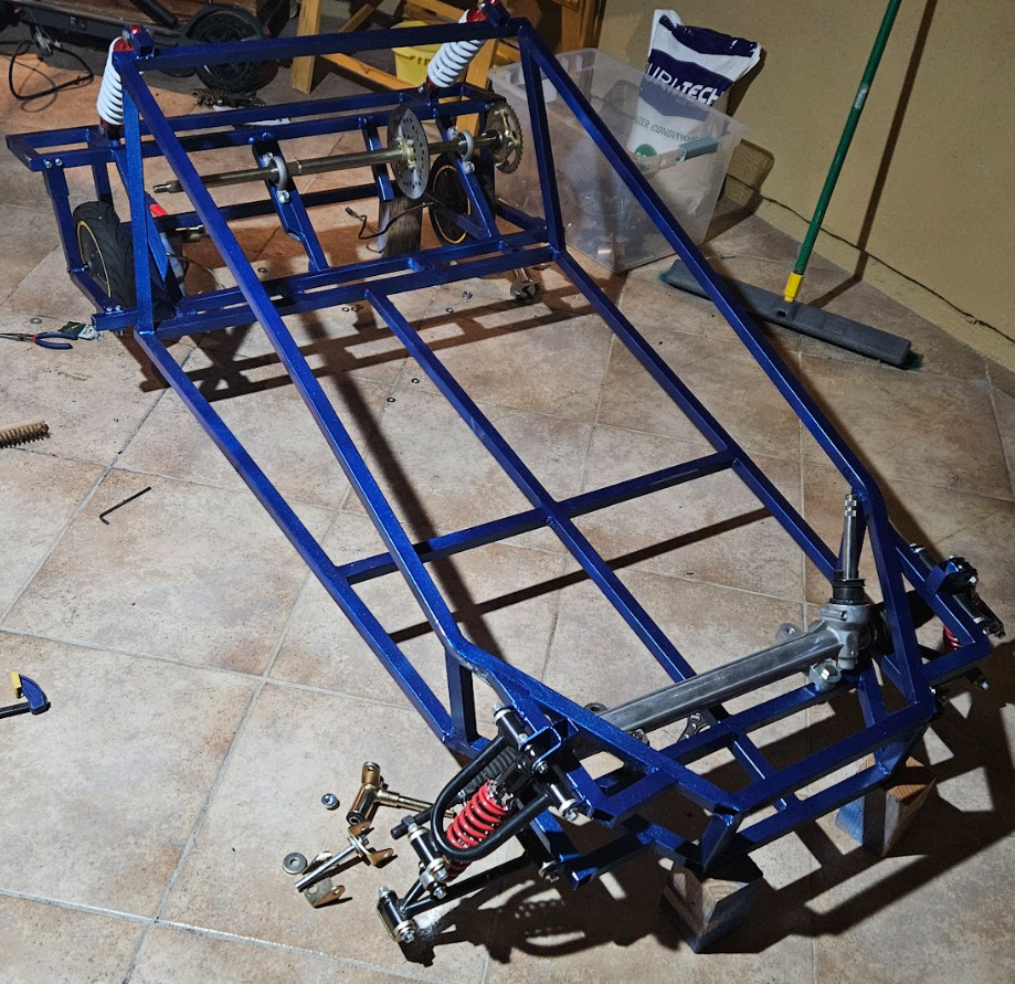
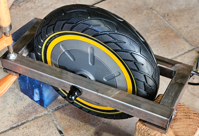
Wheel Cages
You may have noticed the distinct lack of front wheels. That is because escooter motors must be attained from both sides. This is easy to do on the back, but significantly more difficult when those wheels have to rotate.
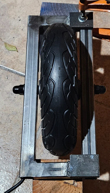
My solution to this is what I call "wheel cages" which are essentially boxes that grab both sides of the wheel and have mountpoints for the tie rod ends of the steering rack.
These wheel cages additionally contain washers welded to the outside, which mate with a key in the motor shaft. This is extremely important as it prevents the shaft from rotating before the wheel.
SEAT
The seat build had always been intended to be dropped into the design after the frame was completed. I was unsure of what tolerance issues might come up during the frame build, so the seat would be designed around the physical cart to some extent. That said, I did have a plan for how the seat would come together in CAD, as I wanted to ensure it was low to the ground but still had flip up storage.
this seat is made from simple 2x4s and plywood. I tacked on memory foam and fake leather for added cushioning. Building this seat really reminded me of how much easier wood is to cut and work with. Metal just requires more effort and steel is especially difficult.
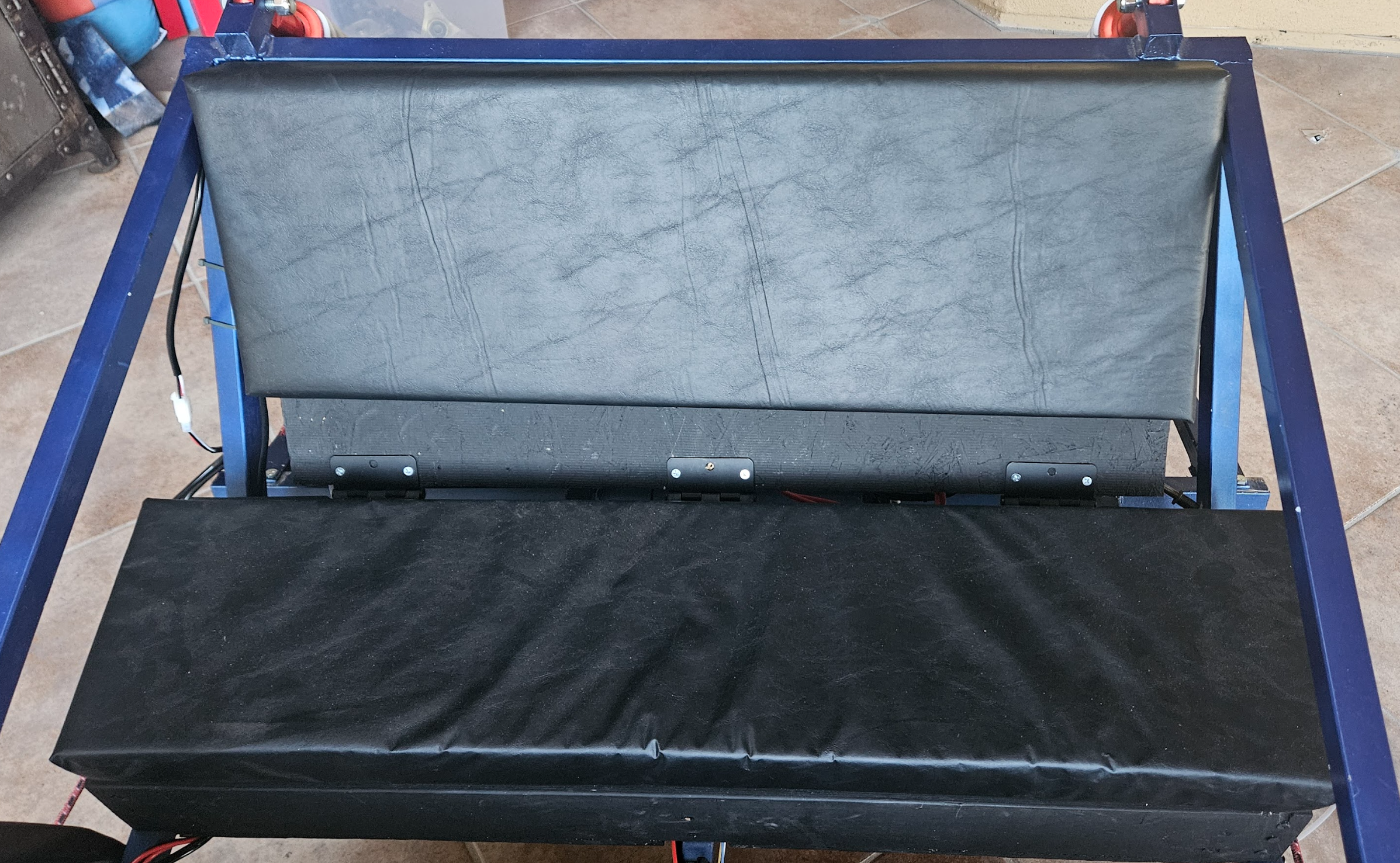
I wanted to ensure the seat could fit a drink horizontally inside without compromising on seat height. This led to a unique folding design where the top plywood is inset into the 2x4 rather than resting on top. The back rest of the seat is also hinged. This allows the back of the seat to lift forward for easy access at electronics behind it.
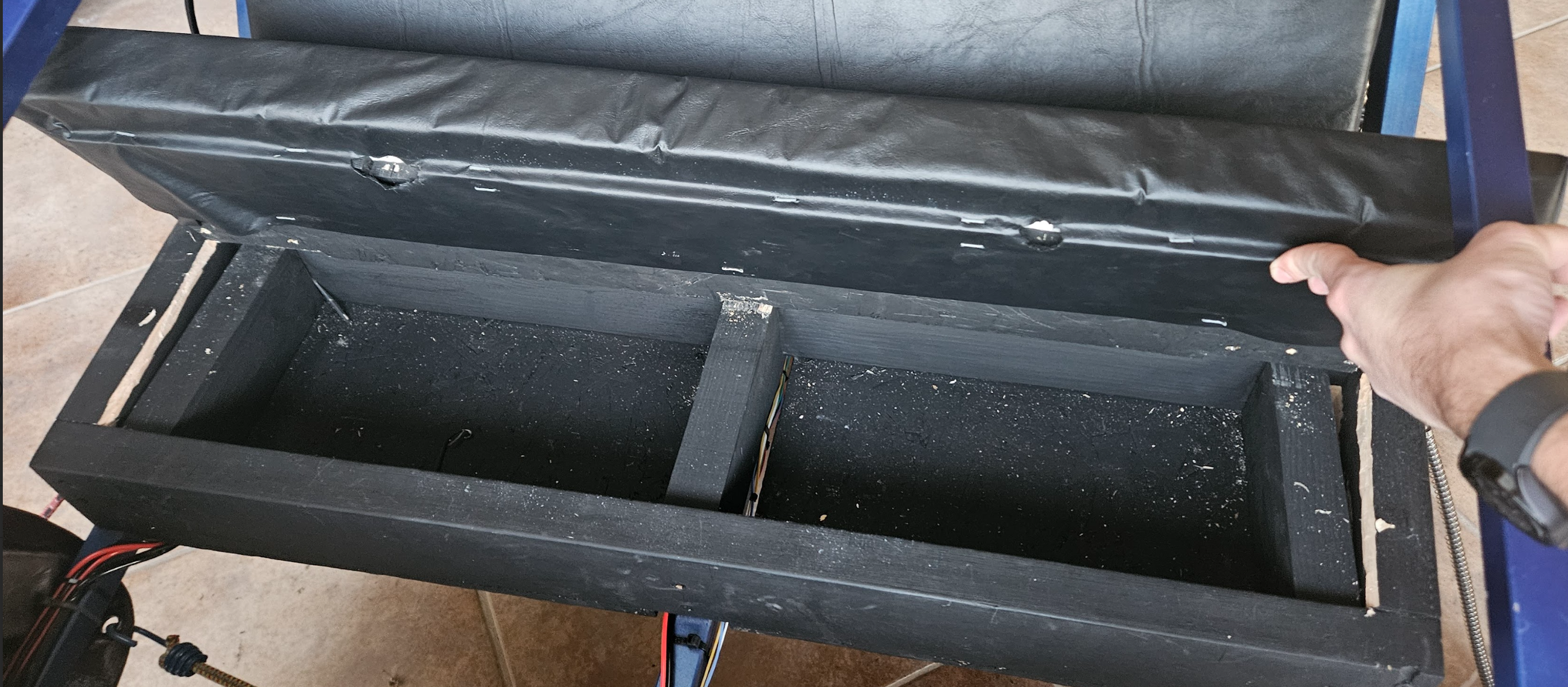
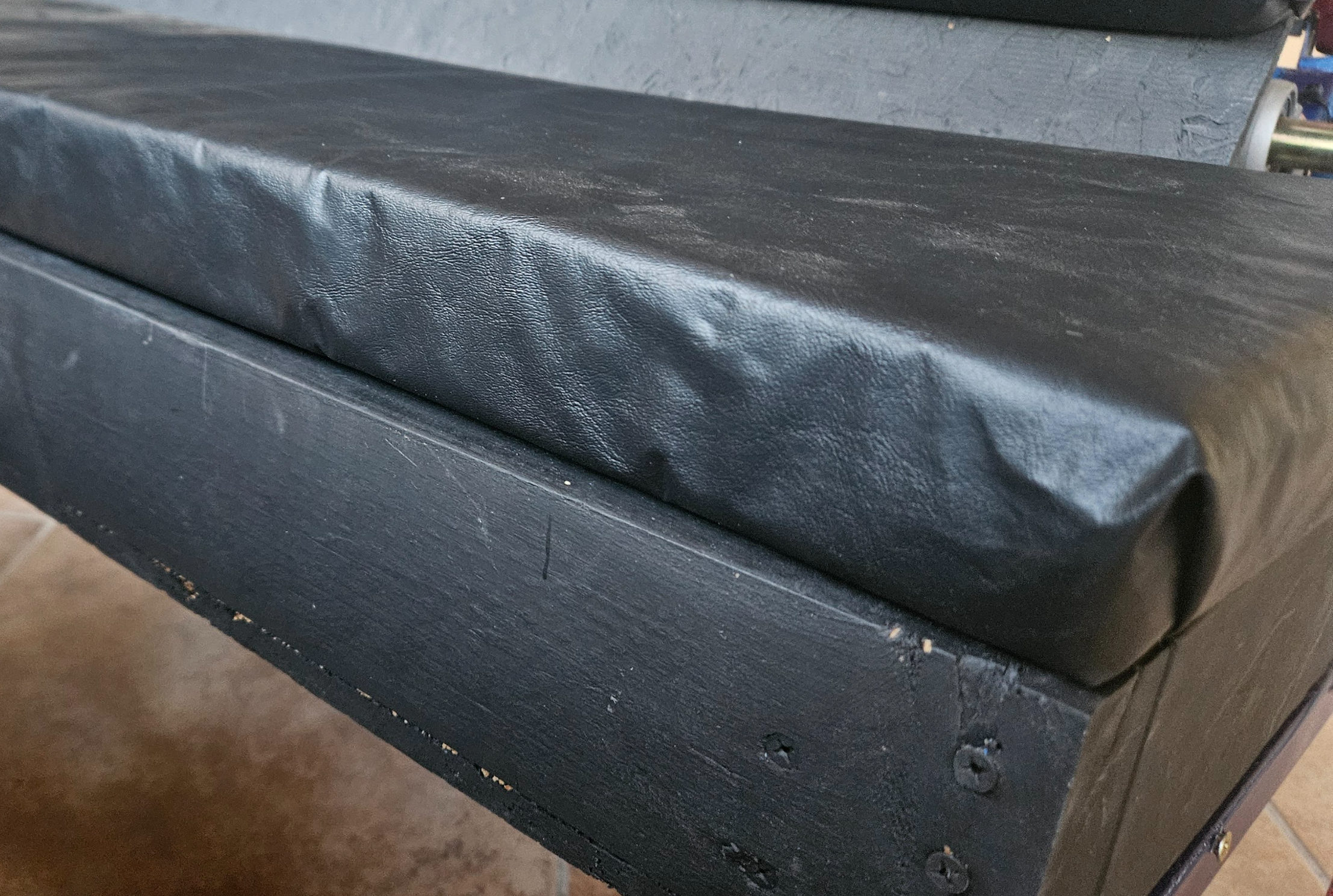
The Upholstery by far the most difficult part. First, the memory foam had to be adhered to the wood, which I did by using a spray adhesive. This worked really well. The problem was the leather. This has to be stretched tight to avoid feeling baggy.
This was easy to do for the back rest, but I definitely messed it up on the bottom. Some day I will come back and redo the bottom leather canvas, but right now its not a big concern.
ELECTRICAL
This is by far the most difficult part of this project. You have to deal with high voltage, high currents, long data lines, and sensitive electronics. This is also where I have spent the most money on the project, with the motor drivers alone costing $400. This doesn't include the price tag of batteries, brain, and buck converters. Here is a more cohesive breakdown.
| Item | Brand | Price | Quantity | Total |
| Motor Driver (Powertrain) | Flipsky Dual FESC 75100 75V 100A | $200 | 2 | $400 |
| Motor Driver (Steering) | DRV 8824 | $20 | 5 | $20 |
| Processor (Dash + Powertrain) | Raspberry Pi 5 w/ Cooler | $120 | 1 | $120 |
| Processor (Steering) | Raspberry Pi Pico W | $5 | 1 | $5 |
| Battery | 36V 7.8Ah Generic E-scooter Battery | $40 | 2 | $80 |
| High Voltage Switch | Apiele LW28-63 | $5 | 1 | $5 |
| Fuse Box | Generic Car/Trailer Fuse Box | $20 | 1 | $20 |
| Buck Converter | Generic DC 6-40V 300W Buck | $15 | 3 | $45 |
| Multimeter and Ammeter | Generic 120V 50A Voltmeter w/ Current Clamp | $20 | 1 | $20 |
| Data Transfer Wire | 360' 22 AWG Strand Core Tinned Copper | $30 | 360' | $30 |
| Power Transfer Wire | 100' 12 AWG Strand Core Copper | $15 | 100' | $15 |
| Data Transfer Connector | JST SM Connector | $10 | Assortment Kit | $10 |
| Power Transfer Connector (Motor) | MT60 Bullet Connector | $15 | Assortment Kit | $15 |
| Power Transfer Connector (Battery) | Anderson Powerpull ASMFP30-2X1-RK | $15 | Assortment Kit | $15 |
| Power Transfer Connector (Motor Driver) | XT90H Pre-Crimped w/ 10 AWG wire | $5 | 2 | $10 |
| Screw Terminal Block | JoinfWorld 55A Block w/ Cover | $10 | 2 | $20 |
| Headlights | Nilight 60W Offroad Truck Lights | $20 | 1 | $20 |
| Accelerator Pedal | 5v Metal Hall Effect Sensor Pedal | $20 | 1 | $20 |
| TOTAL | $870 |
If I have learned anything from industry, electronics are ALWAYS the problem if you cheap out. Murphy's law seems to apply to electronics more than other subsystems, and if you see a problem in electronics, its almost always too late to fix it.
Another problem with all these components is "Integration Hell", which I have definitely experienced with perfecting the Pi-Powertrain Motor Driver handoff.
All of these electronics rest on the Rear Electronics panel, which is mounted in the back of the vehicle. I noticed that this panel was making a lot of noise when bolted directly to the frame, so I isolated the entire panel from the frame with rubber gussets. These will also serve to dampen vibrations.

Electronics Panel
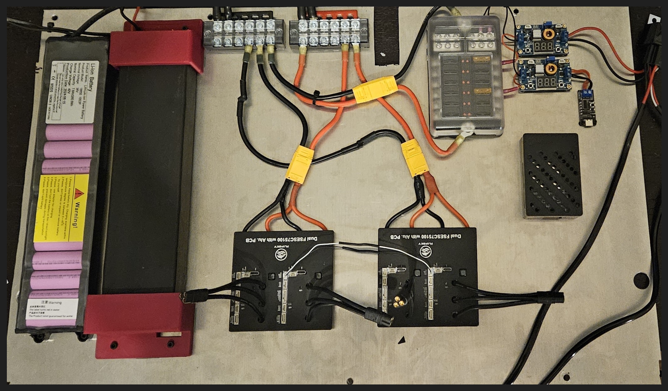
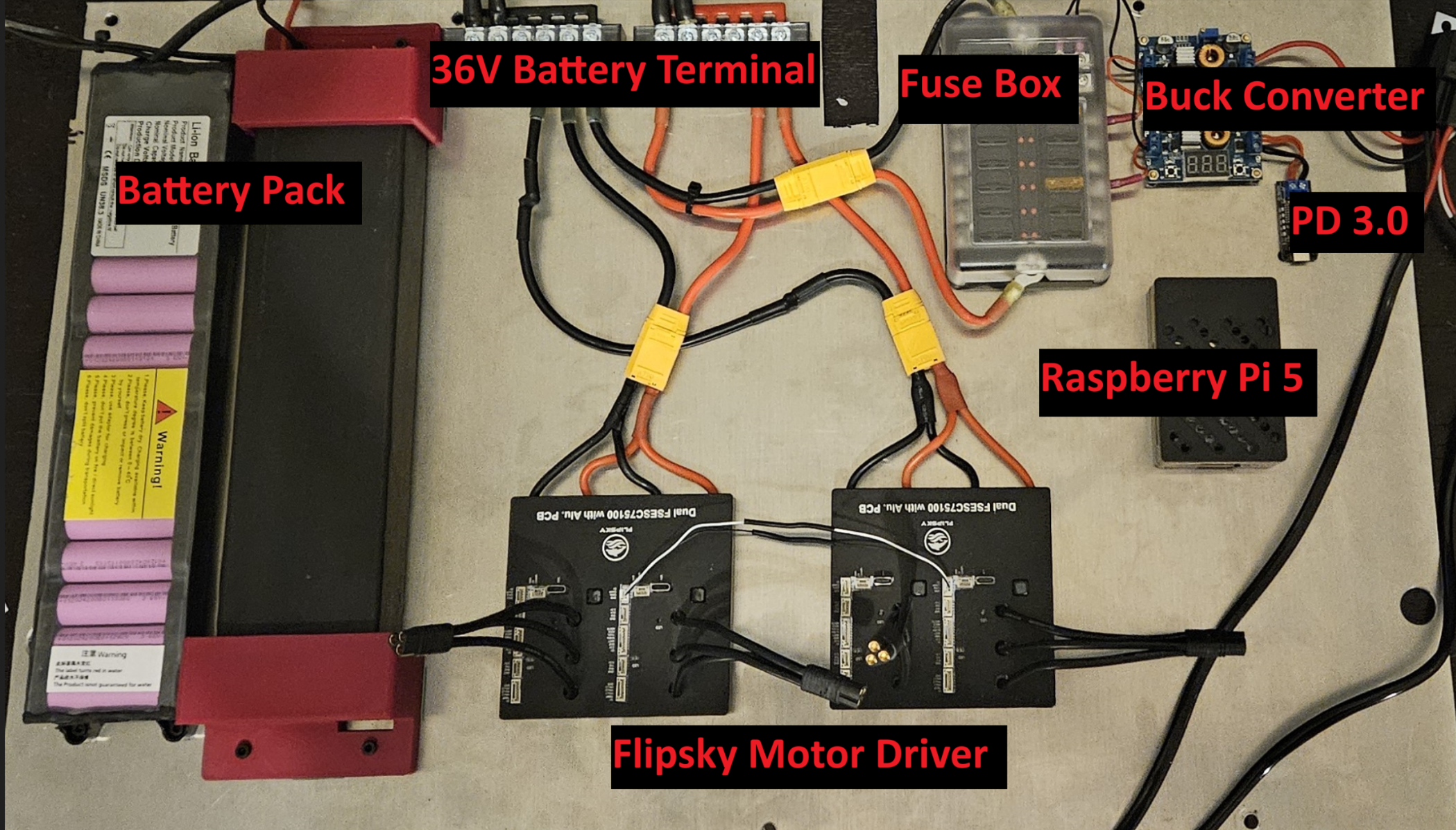
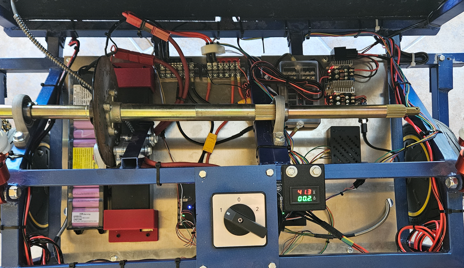
The electronics panel is not terribly complex all things considered. Two 36v 7.5Ah batteries are wired in parallel and connected to the two upper screw terminal blocks. Those blocks feed down into the motor drivers and the fuse box. The fuse box outputs to two buck converters (one for a type-C PD and one for the headlights). The PD3.0 Outputs to the Raspberry Pi USB in, providing additional power surge protection. Finally, the fuse box additionally connects to the steering motor driver breakout board.
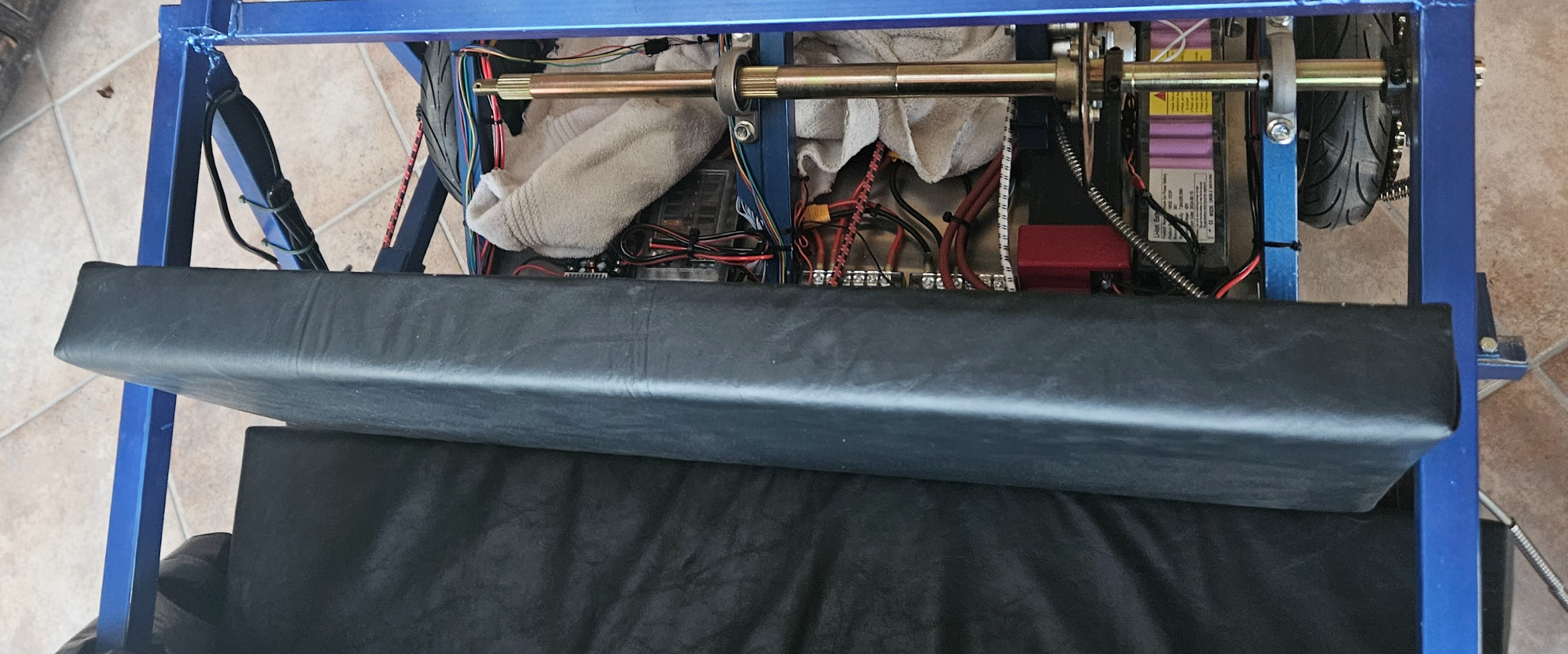
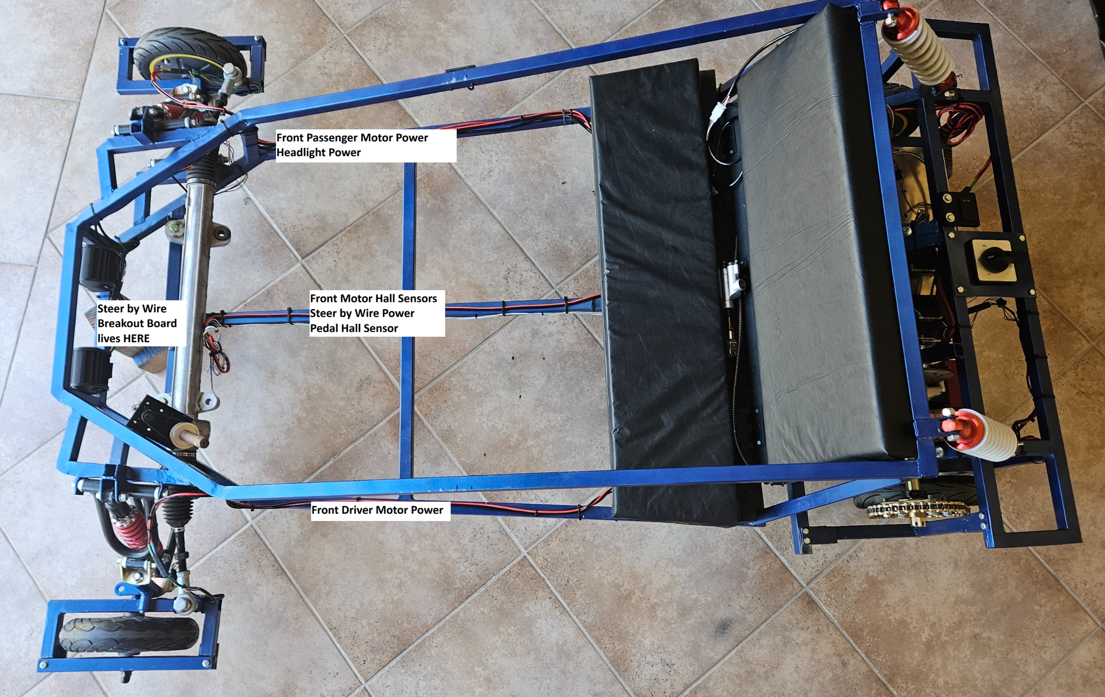
Electronics Mounted on Vehicle
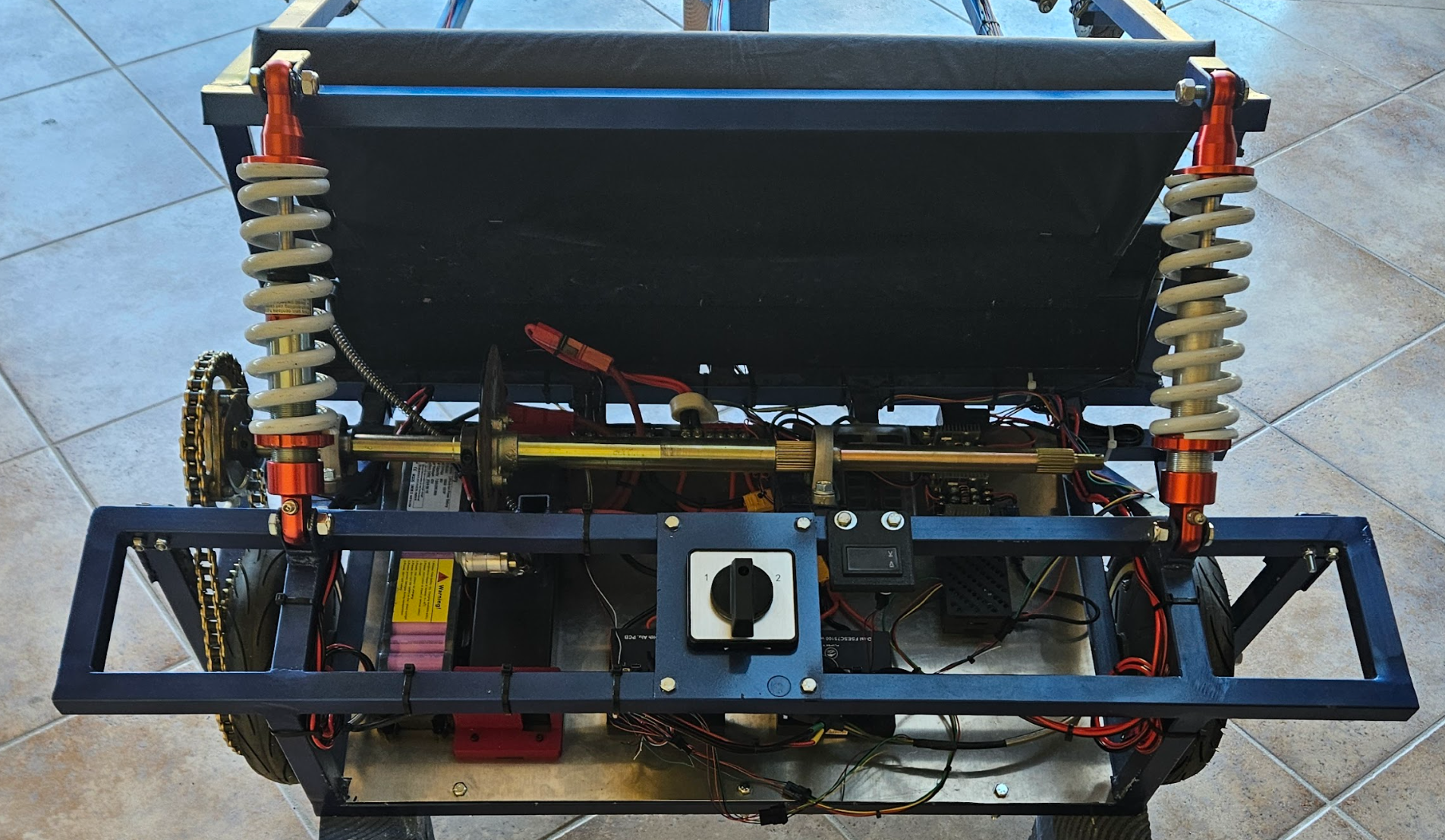
The only real differences between the vehicle and the panel are the addition of the motors, switch, and voltmeter. Quick connects were hugely important in this process, as I want the electronics panel to be easily removable when the vehicle will not be used for an extended period of time.
I used Anderson Powerpulls on to connect the battery to the switch since these have massive current and voltage ratings. The MT60 Bullet connecters are some of my favorite connecters ever. They solder directly to the wire, can fit through very tight spaces, and have incredible clutch power. I used JST SM locking connecters for anything data. I love them, but crimping them in place requires some serious skill, especially when you don't have the fancy Molex Dupont crimper.
Wiring
The wiring for the kart is zip tied directly to the tube and runs around the entire frame. Electrical Noise is a definite issue when you have a high power system and serial communication. I have negated this by simply not running power on the same frame member as coms. When I absolutely have to run them on the same member (like the center bar), the are on opposite sides of the tube.
Motors and Motor Driving
The motors I selected sort of fell into my lap when I found them for a steal on an auction website. I bought 6 total Ninebot G30Max 3 phase BLDC Motors for about $150 give or take. So far, I have not burnt out any of these motors (I've come close), but I have two spares for when this inevitably happens.
The Flipsky Dual FESC 75100 is a seriously awesome driver for this application. Its basically two 75100 drivers stuck together on the same PCB, with CAN traces between them. They support multiple different drive modes (Field Orient Control, High Frequency Injection, Any Sensor Based) and have regenerative braking capacity. These can even send and receive UART Data, allowing me to control them with the Pi and even display a digital dash. With a CAN bridge between the two boards, I can see all four motor drivers on my computer, and edit almost any parameter associated with vehicle function.
Right now, these boards take an input from my Hall Effect pedal. This input is then run through an internal ADC, and processed into either forward or brake current. Here is a video of this mechanism in action!