


Project Details
Overview
This project focuses on building an accelerated aging test bench to study how ADAS sensors - LiDAR, radar, and cameras - change over years of use. Instead of waiting a decade for real-world degradation, the goal was to expose these sensors to temperature, humidity, and vibration that simulate long-term road conditions in just a few months. When I joined the project, the original setup used coil springs, but they transmitted almost all the vibration directly into the sensor plate. I rebuilt the system around a tensegrity-style elastic cable suspension, modeled the entire structure in SolidWorks, and ran ANSYS modal/harmonic simulations to make sure the new design actually isolated the right vibration ranges (mostly 30–40 Hz).
Research Goals
- Accelerate multi-year ADAS sensor degradation using combined environmental stresses
- Keep the sensor plate isolated so the test bench doesn’t affect readings
- Support future work on sensor lifespan modeling and calibration drift
- Ensure the design fits and works inside an environmental test chamber
System Architecture
Base Plate & Structural Platform
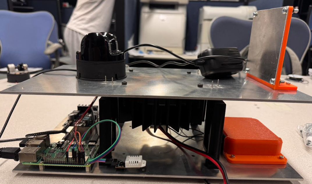
The lower assembly is built around a machined 6061 aluminum base plate designed to mount securely inside the environmental chamber. Its job is to provide a rigid foundation for the vibration motor and electronics while keeping all hardware stable during long-duration tests.
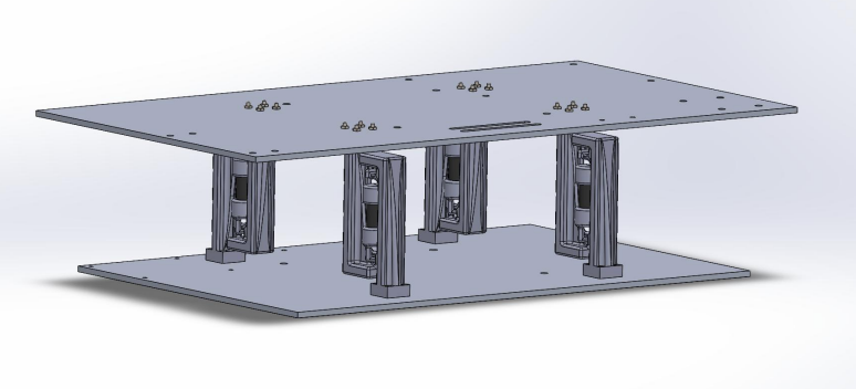
Tensegrity Vibration Isolation Assembly
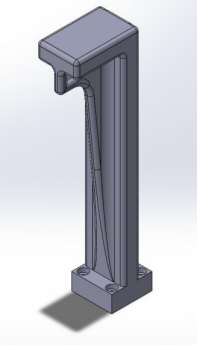
Above the base, the sensor plate is suspended using elastic tension cords arranged in a tensegrity layout. This geometry allows the plate to flex and move independently of the base, and after several iterations of improving hook geometry and cable routing, the suspended system held tension reliably under vibration.

Sensor Mounting & Instrumentation
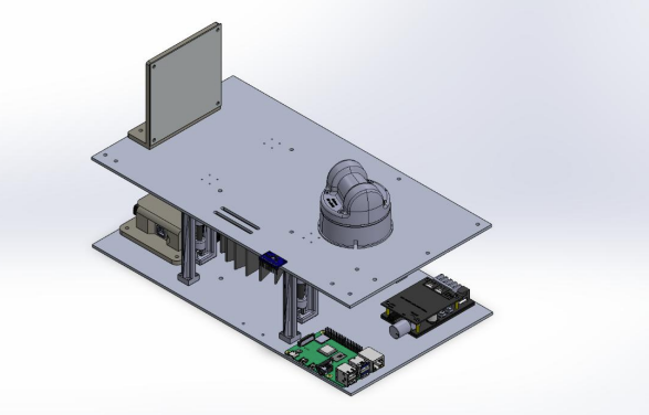
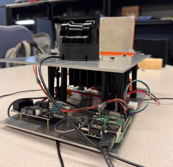
The upper plate supports the LiDAR, radar, and camera, allowing each sensor to experience controlled mechanical and environmental stress. Their mounting positions were chosen to ensure consistent exposure across tests and to keep the sensor field of view unobstructed during motion.
Data Acquisition & Test Configuration
A Raspberry Pi–based DAQ system on the lower plate manages sensor setup and logs output throughout chamber cycles. Because it remains on the stationary side of the structure, the Pi captures clean data while the suspended plate moves, making it easy to track changes in sensor behavior over extended testing periods.
Design, Prototyping & Iteration
| Challenge | Response |
| Springs failed to isolate vibration | Replaced with tensegrity elastic cable system |
| Cable hooks detached under load | Redesigned hooks + adjusted cable lengths |
| Plate deformation & tolerance issues | Modified aluminum plate geometry and mounting points |
| Chamber compatibility | Repositioned sensor mounts & rerouted wiring harnesses |
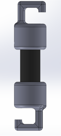
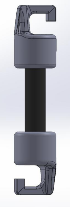
I went through several rounds of redesigning the cord hooks after seeing how easily they slipped off in early prototypes. The revised design below held tension properly and didn’t fail during simulation or bench tests.
Simulation & Verification
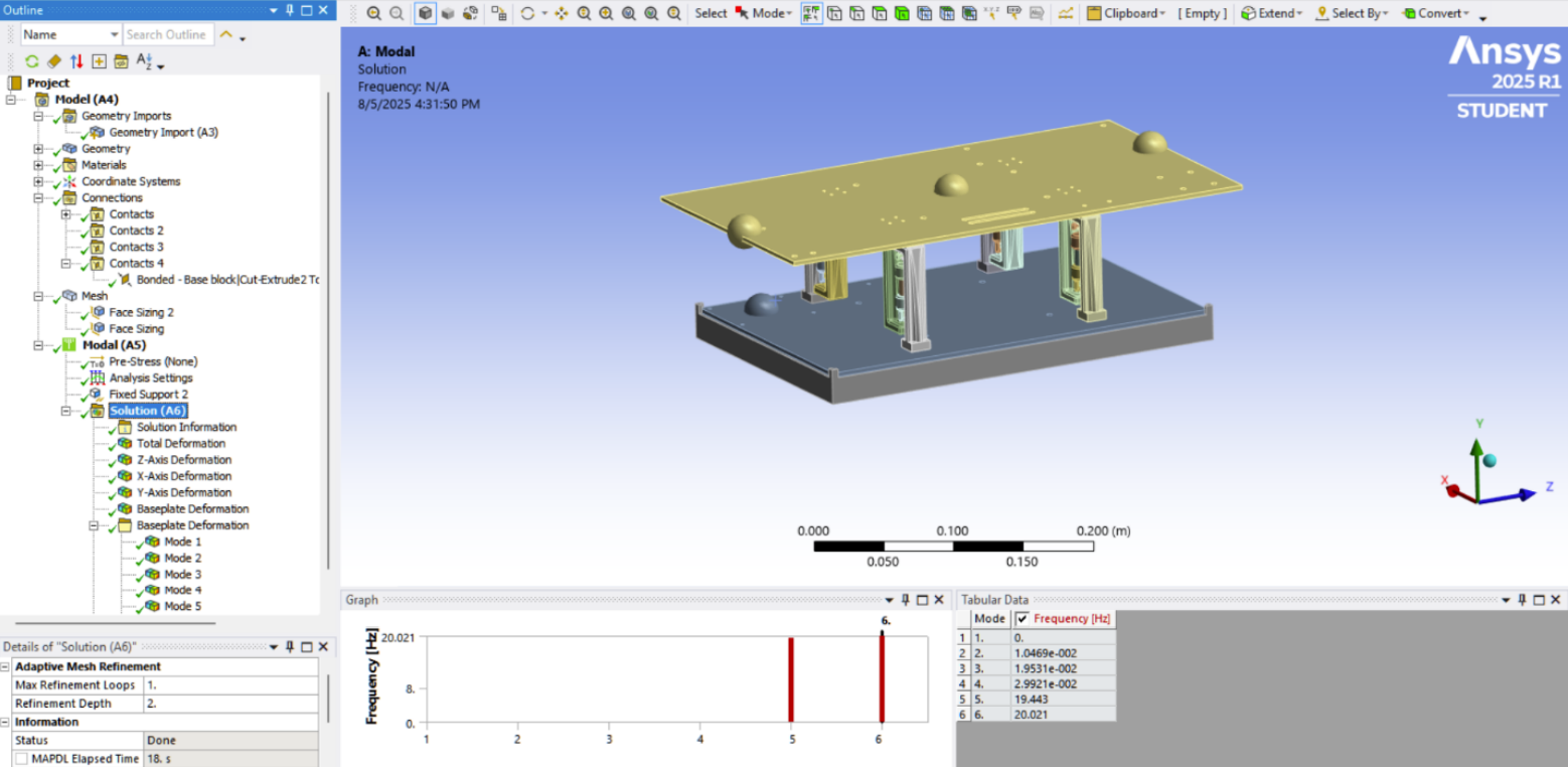
Before building the final version, I ran modal and harmonic simulations in ANSYS to make sure the tensegrity setup would actually isolate vibration the way we needed. The main goal was to keep the upper plate (where the LiDAR, radar, and camera sit) moving while the base plate stays almost still, especially in the 30–40 Hz range where a lot of real road vibration lives.
Materials Used in the Model
| Component | Material |
| Upper and lower plates | 6061-T6 Aluminum |
| Tension cables | Elastic shock cord |
| Printed brackets and hooks | PLA |
| Fasteners and mounting hardware | Stainless steel (304) |
How I Set Up the Simulation
- The lower plate was fixed at the mounting holes to match how it bolts into the chamber.
- The tension cords were set up as tension-only elements with a small preload, like the real assembly.
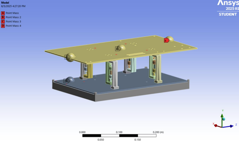
- I added sensor mass to the upper plate to represent the LiDAR, radar, and camera during testing.
- The system was excited with a frequency sweep from 5–80 Hz, with extra attention on 30–40 Hz.
What I Looked For
I mainly watched how much each plate moved relative to the other, and whether the system’s natural modes matched what we expect in a tensegrity layout (a lot of motion at the suspended plate, very little at the base).
What I found
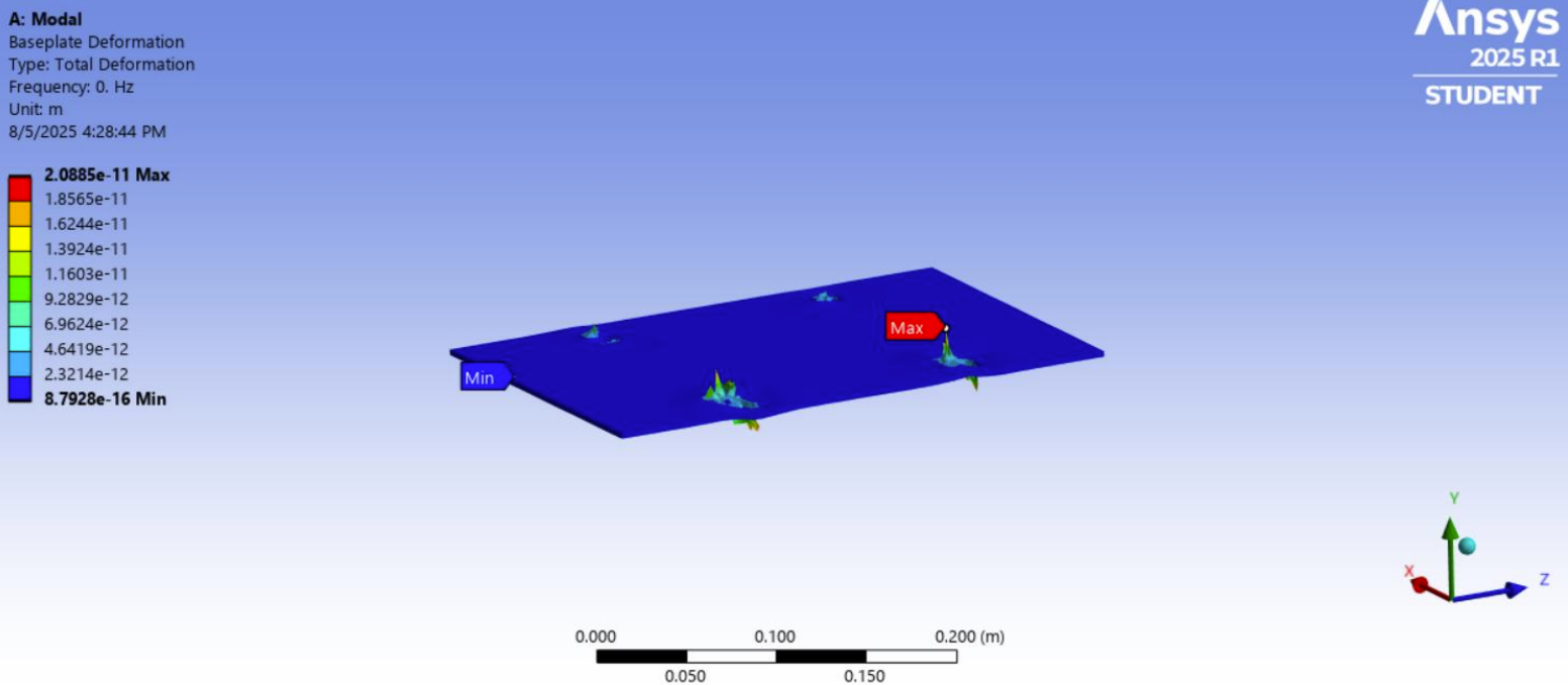
Before running the tensegrity version, I also simulated the original spring-based design (first picture) that was being used before I joined the project. In that model, the base plate and upper plate were basically moving together, meaning almost all the vibration was transferring straight through the structure. That would make it almost impossible to measure sensor aging accurately because the bench itself would be adding noise into the data.
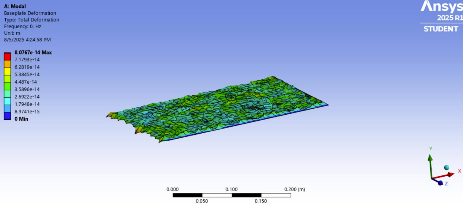
With the new tensegrity setup, the results were noticeably different (second picture). The upper plate moved much more than the lower plate in the 30–40 Hz range, which is where a lot of real road vibration happens for ADAS hardware. The base plate stayed almost still, which is exactly what we needed so that any performance changes in LiDAR, radar, or camera readings would come from environmental stress, not from the test bench interfering.
Outcomes
By the end of the research term, I delivered a chamber-ready accelerated aging platform capable of supporting long-term ADAS sensor evaluation. The system:
- Successfully isolates upper-plate vibration using tensegrity tensioning
- Enables controlled temperature, humidity, and vibration exposure
- Supports sensor lifespan modeling and calibration drift research
- Establishes a foundation for future ADAS durability testing
Skills Demonstrated
- ANSYS Modal Analysis & Structural Simulation
- Vibration Isolation & Tensegrity System Design
- SolidWorks & Assembly Design
- 3D Printing & Machining
- Sensor Instrumentation & DAQ Integration