


Project Details
Overview
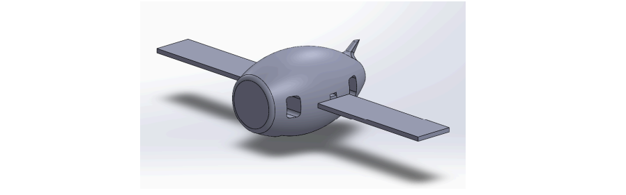
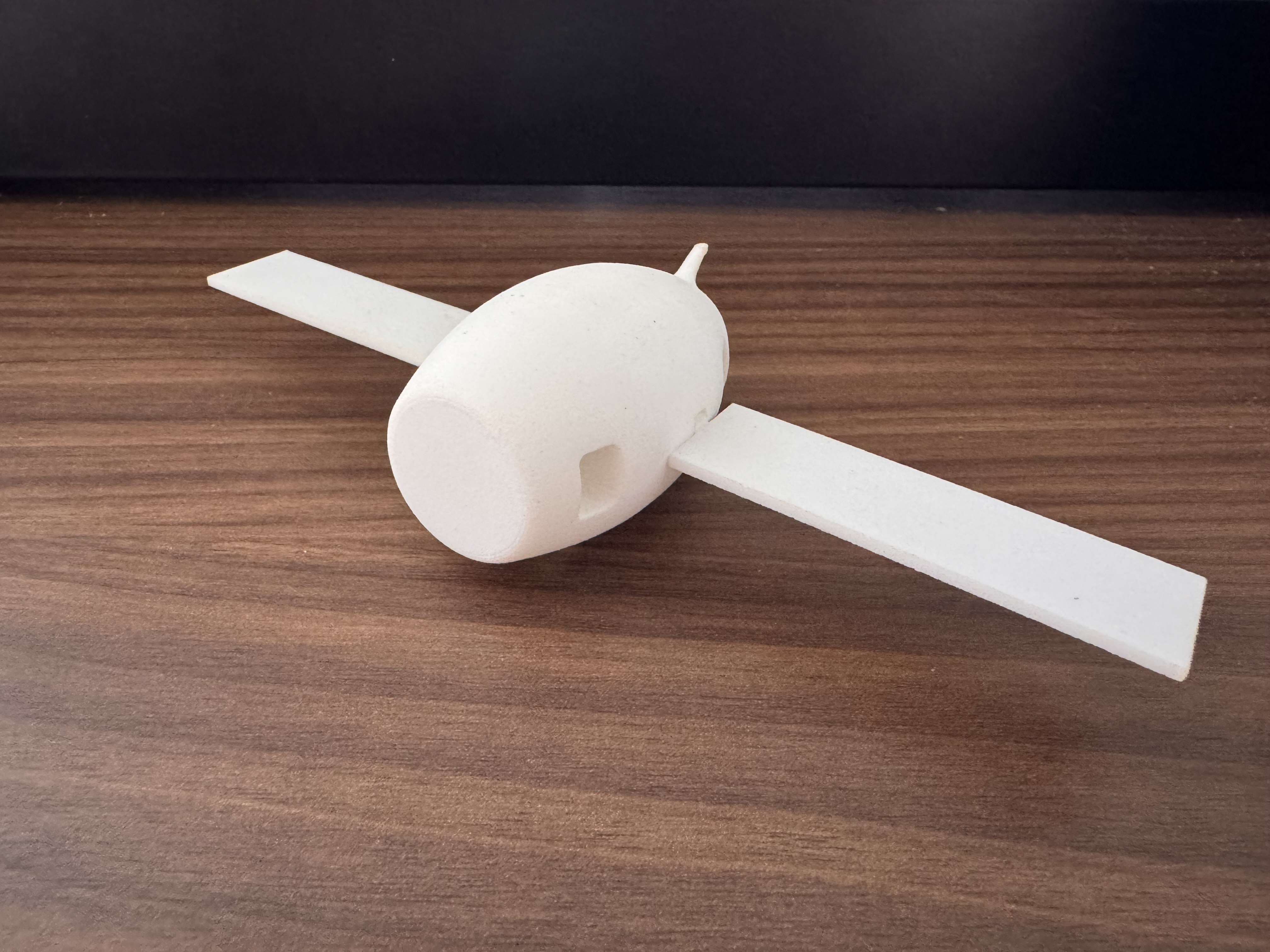
SolidFlight is a modular, tool-less 3D-printed airplane that I designed for ME 1670: Engineering Graphics & Design at Georgia Tech. I created the aircraft to demonstrate fundamental aerospace geometry and to showcase how snap-fit and slip-fit joints can enable quick assembly and disassembly without screws, glue, or tools. The plane consists of a fuselage, wings, and tail section, all modeled in SolidWorks with Design for Additive Manufacturing (DFM) considerations to ensure printability, strength, and reliable fit.
Design Goals
Create a modular airplane that can be assembled and taken apart repeatedly without damage
Apply snap-fit and slip-fit mechanisms suitable for FDM/SLS 3D printing
Reduce support material and improve surface quality through DFM decisions
Validate tolerances through iterative prototyping and measurement
System Design
Fuselage + Tail Structure
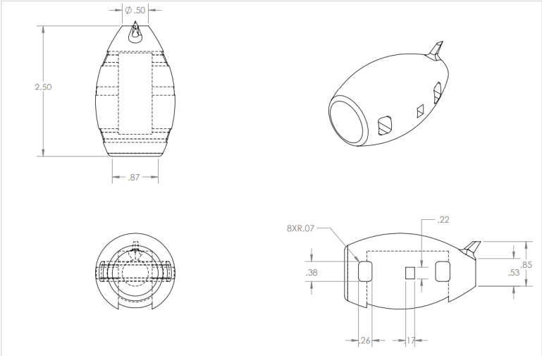
The body is a single continuous lofted shape with the vertical and horizontal tail surfaces built into the fuselage. This simplified the model, improved strength, and eliminated alignment issues between tail components. Key features include: tail geometry fully fused to the body, wing mounting pockets and window cutouts.
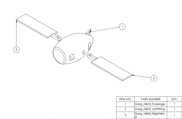
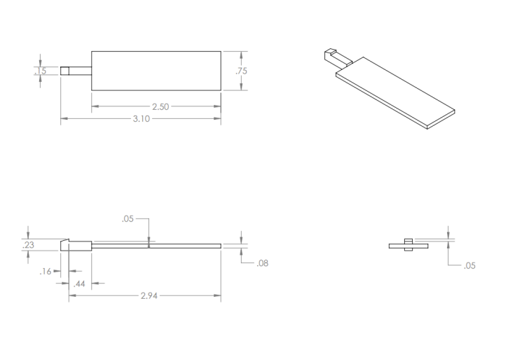
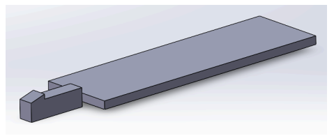
Snap-Fit Wing Geometry
The wings were modeled as separate components and attach to the fuselage through snap-fit tab connectors. Initial clearance was designed at 0.3 mm, optimized through tolerance testing to ensure a secure but removable fit. Key features include: extruded wing planform, snap-fit tab and fuselage slot interface, fillets for strength at load-bearing regions.
Design for Additive Manufacturing
To ensure a reliable print and strong mechanical performance, I used the following strategies:
- Printed components flat to minimize warping and maximize layer adhesion
- Limited overhangs to <45° for support-free geometry
- Added chamfers and fillets to eliminate sharp unsupported edges
- Tuned tolerance ranges to compensate for printer shrinkage and surface variation
Tolerance Analysis & Iteration
During the first 3D-printed prototype, small-feature dimensions showed greater variation than expected. While large geometry printed with excellent accuracy, the snap-fit interfaces printed tighter than designed, causing higher insertion force and difficult disassembly. The values below highlight the most critical tolerance deviations that informed the next design iteration.
| Feature | CAD (in) | Printed (in) | Percent Difference |
| Snap-Fit clearance | 0.012 | 0.006 | -50% |
| Snap-fit slot width | 0.197 | 0.191 | -3% |
| Wing tab width | 0.197 | 0.192 | -2.6% |
| Overall wing length | 1.969 | 1.976 | +0.4% |
Outcomes
By the end of the project, I had a fully functional, modular airplane model that:
- Prints reliably on consumer 3D Printers
- Demonstrates aerospace component relationships in an educational and interactive way
- Assembles and disassembles without tools or fasteners
- Serves as a reusable and scalable teaching aid for CAD, prototyping, and DFM concepts
Skills Demonstrated
- SolidWorks part modeling & assemblies (lofts, fillets, extruded cuts, tolerancing)
- Design for Additive Manufacturing (snap-fits, print orientation, support reduction)
- Rapid prototyping with 3D Printing (FDM/SLS)
- Tolerance analysis & measurement
- Iterative design and problem solving