


Project Details
Overview
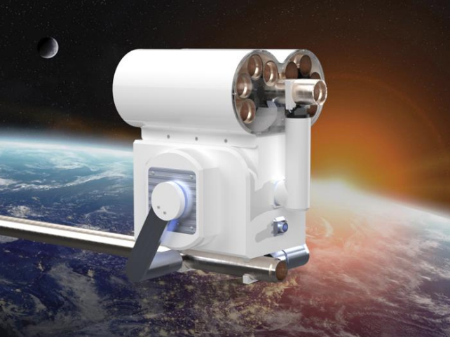
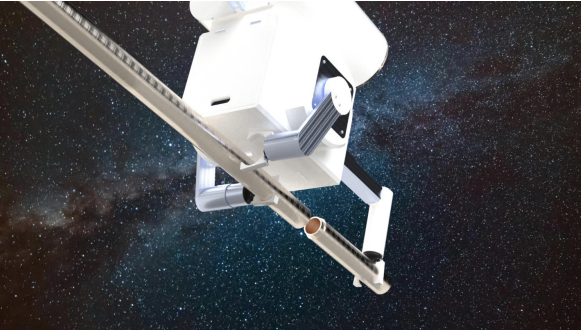
The Cosmic Constructors Space-Assembly Robot is a conceptual robotic system designed to autonomously assemble truss structures in microgravity. This project explores how modular robots can support orbital construction tasks that are impossible for humans due to the mechanical, thermal, and environmental constraints of space. The final design was built entirely in SolidWorks and focuses on mechanism design, structural layout, and kinematic feasibility for multi DOF assembly operations.
Problem Context
In-space construction is becoming increasingly important for large-scale structures such as space stations, antenna arrays, and solar power platforms. Traditional construction methods do not translate into microgravity environments, where every component must be designed for autonomous manipulation, precise motion, and reliable alignment. This project investigates a feasible robotic solution for assembling standardized truss components in orbit using mechanical simplicity and modular subassemblies.
Objectives
- Develop a SolidWorks-based robotic architecture suitable for microgravity construction tasks
- Create mechanisms capable of gripping, aligning, and attaching truss elements
- Integrate multiple independently modeled components into a unified assembly with correct tolerances
- Demonstrate kinematic feasibility of multi-axis robotic operations
System Architecture
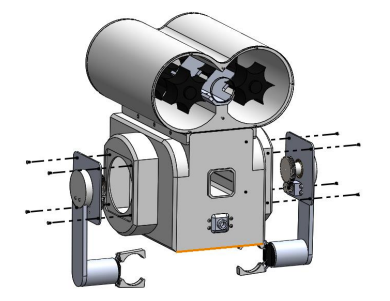
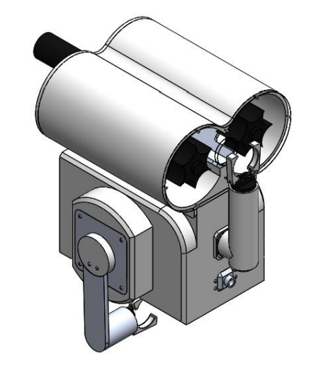
The robot consists of several mechanically interdependent subsystems, each modeled separately and integrated into a full assembly:
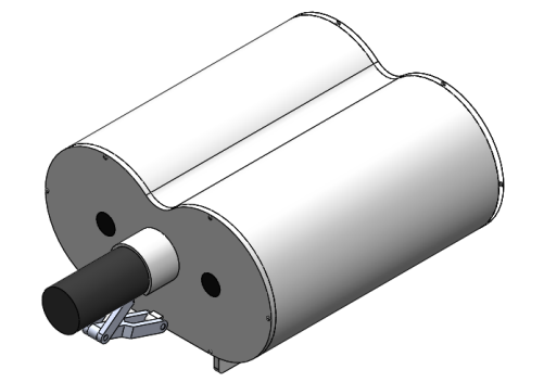
1. Chassis/Structural Frame
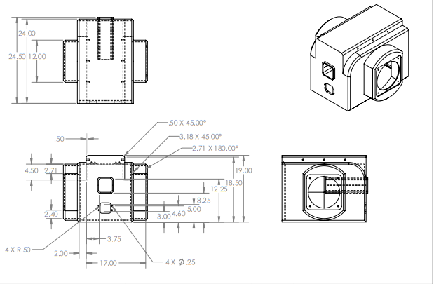
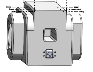
The robot’s body is a compact housing that supports the motion systems and keeps everything rigid during assembly tasks. Its size, shape, and internal layout were chosen to stay balanced in microgravity while providing solid mounting points for the hinge mechanisms, camera enclosure, and truss-handling elements.
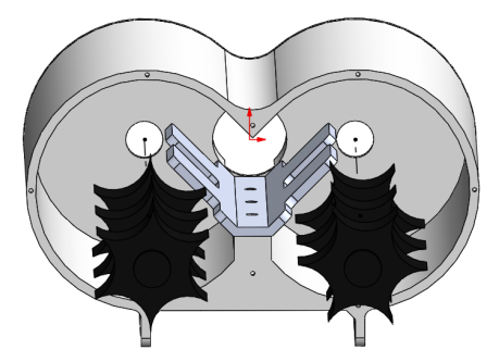
2. Hinge & Joint Mechanism
The joints were modeled as simple hinge assemblies with defined angular limits to mimic how a real microgravity robot would control its reach. These joints allow the robot to rotate, grip, and position truss pieces without drifting off-axis, and were tuned in SolidWorks using mates and link geometry to ensure smooth, realistic movement.
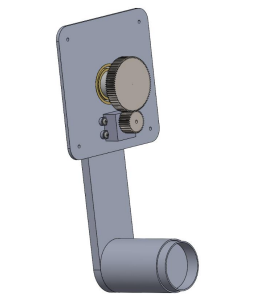
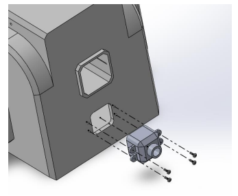
3. Camera & Sensor Housing
A small camera enclosure was added to represent where navigation and alignment sensors would sit. Its placement gives the robot a clear line of sight to the truss components it’s manipulating, helping with tasks like edge detection, alignment verification, and general situational awareness in orbit.

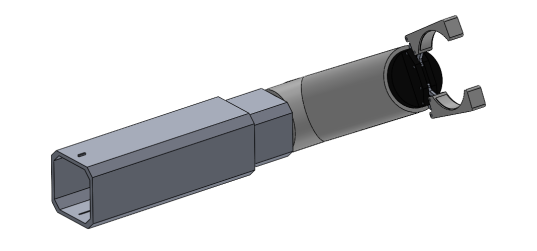
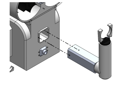
4. Tubing & Truss-Handling Elements
The truss elements were modeled as cylindrical tubes sized for realistic grabbing and alignment. These tubes were included to test whether the robot’s joints could actually reach, rotate, and position them in a way that makes sense for microgravity construction.
CAD Modeling & Integration Workflow
- Created individual SolidWorks part files for each subsystem (chassis, hinge assemblies, camera mount, tubular connectors)
- Applied mates, constraints, and tolerances to replicate physical kinematic behavior
- Resolved interferences, alignment issues, and mismatched dimensions through iterative refinement
- Conducted full assembly integration to verify mechanism movement paths and structural coherence
Mechanical Considerations
- Microgravity Requirements: Robot geometry and mass distribution were optimized for zero-gravity handling
- Tolerance Control: Interface features modeled with realistic clearances to allow reliable assembly in an orbital environment
- Kinematic Reach: Joint placements and link lengths chosen to maximize workspace and gripping maneuverability
- Modularity: Subassemblies designed to be independently manufacturable and serviceable
Outcomes
- Delivered a complete SolidWorks assembly demonstrating a feasible robotic system for in-space truss construction
- Produced a mechanically consistent multi DOF robot capable of gripping, rotating, and positioning structural elements
- Resolved all CAD integration challenges, ensuring full compatibility between independently designed parts
- Established a foundation for autonomous construction concepts that rely on coordinated swarm behavior in microgravity
Skills Demonstrated
- SolidWorks Part + Assembly Modeling
- Mechanism + Linkage Design
- CAD Integration & Tolerance Control
- Structural Layout
- Orbital Environment Design Considerations
- Kinematic Simulation