Inspired by the AeroVelo Atlas, this project develops a human-powered quadcopter blade using a NACA-4515 airfoil with chord length and twist angle tailored along the radial span to achieve the lift required for hover. The design process incorporates aerodynamic modeling, including validation of the Vortex Panel Method for predicting lift coefficients across a wide range of angles of attack. By generating optimized chord and twist distributions, the project computes sectional aerodynamic force coefficients, determines the minimum torque needed for the rotor to spin at 15 rad/s, and evaluates the resulting thrust produced by the blade. The final design demonstrates a feasible aerodynamic configuration capable of supporting human-powered hover while remaining within realistic power constraints.
Design of the Rotocraft
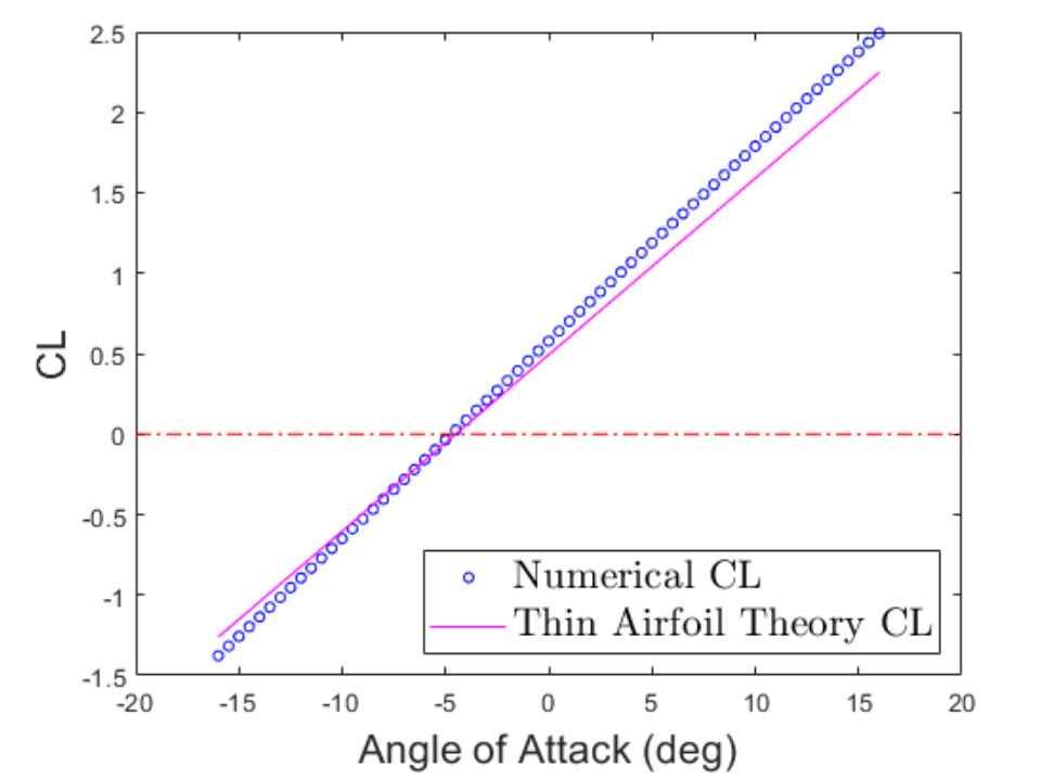
The Coefficient of Lift for the NACA-4515 airfoil shows a strong linear dependence on angle of attack from −16° to +16°. As shown in the comparison figure, results from the Vortex Panel Method closely follow thin-airfoil theory, with a maximum deviation of only 0.24 in CL. Both methods predict a zero-lift condition at approximately −4.5°, confirming the expected zero-lift line for this airfoil.
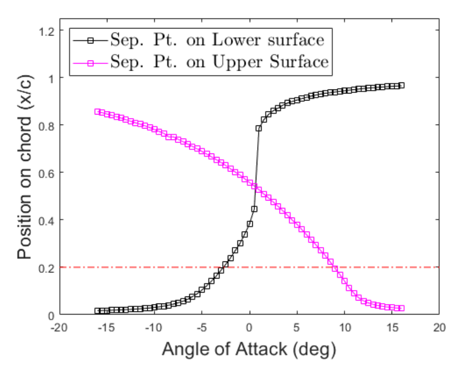
The upper and lower boundary-layer separation points were calculated using Thwaites’ Method and are shown in the corresponding figure. As angle of attack increases, the upper-surface separation point shifts smoothly from the trailing edge toward the leading edge. In contrast, the lower-surface separation point exhibits an S-shaped behavior, jumping rearward near 0° and then flattening for positive angles of attack. Using the upper-surface separation curve, the stall angle is identified at the point where separation moves upstream past the 0.2-chord position, yielding a stall angle of approximately 8.92°.
To construct a quadcopter blade using the NACA-4515 airfoil, the design specifies a chord distribution ranging from 1.5 m at the root to 0.5 m at the tip, extending from a radial position of 1 m to 10 m. Determining the twist angle β(r) requires understanding how the geometric angle of attack α(r) combines with the induced angle of attack Φ(r). The induced angle Φ(r) is calculated from the hover induced-velocity expression and obtained by taking the arctangent of the induced velocity divided by the local tangential velocity. Because Φ(r) varies nonlinearly along the blade while α(r) is defined as a linear function, the resulting twist distribution β(r) must also be nonlinear to satisfy aerodynamic requirements. The figure below illustrates this relationship.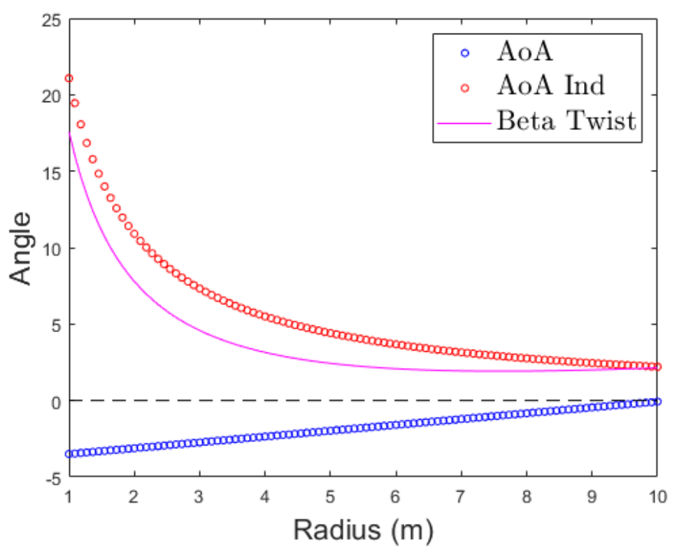
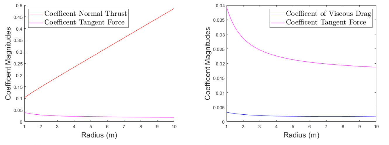
The next step is to compute the theoretical lift coefficient CL using the zero-lift angle of −4.5°. Sectional force coefficients are then obtained by projecting CL into the normal and tangential directions using cos(Φ(r)) and sin(Φ(r)), respectively. The normal component contributes to finding the blade’s full thrust, while the tangential component can be used to determine the aerodynamic moment resistance. Sectional viscous-drag coefficients are also calculated for each radial position. As shown in the figures below, the normal thrust coefficient increases approximately linearly along the blade, whereas both the tangential force coefficient and viscous-drag coefficient decrease inversely and with a much smaller magnitude.
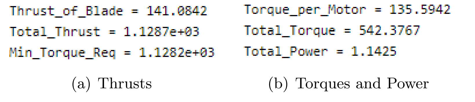
The next figure shows the thrust Tb produced by the optimized blade, the total thrust Ttot generated by the quadcopter, and the minimum thrust Tmin required to hover. The total thrust is obtained by multiplying the thrust from one blade by the number of blades and rotors, while the hover requirement is simply the weight of the vehicle. The figure also presents the torque produced by each motor, the total system torque, and the resulting power consumption. Total torque is calculated by scaling the per-motor torque across all four motors, and the overall power requirement is found by multiplying this torque by the operating speed of 15 rad/s.
Method to Optimize Power
The primary objective was to minimize the power required for hover to stay below the 1.5 hp target. I began by defining linear distributions for both α(r) and β(r) to make the design space predictable and easy to tune. The chord distribution c(r) was also set as a linear taper from 1.5 m to 0.5 m. To reduce power consumption, I iteratively lowered the angle-of-attack range, starting from the smallest feasible α(r) values and expanding the range only until the generated thrust exceeded the quadcopter’s weight. After several iterations, the optimal range was found to be α(r) = [–3.5°, –0.07°], resulting in a total power requirement of 1.1425 hp. This final design meets the hover condition while using only 76% of the allowable 1.5 hp, representing a significant optimization success.
To determine whether a human could realistically power the quadcopter, I compared the required hover power of 1.1425 hp to the short-duration power output an average person can generate. A useful physical analogy is the power produced when running up a flight of stairs, since this motion involves lifting one’s body weight vertically over a short burst of time. Assuming an average person of 63.5 kg runs at an effective velocity of about 5 mph (2.24 m/s) along a 45° incline, the vertical component of this motion produces a power output of approximately 1.32 hp using . Because stair climbing is not the most efficient way for humans to generate power—and still exceeds the 1.1425 hp required—the analysis shows that an average, reasonably fit human could supply enough power to sustain a 15-second hover. This confirms that the optimized blade design meets the human-power feasibility constraint.
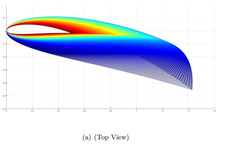
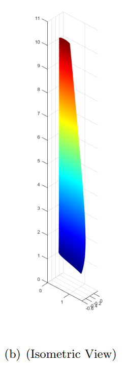
3-D Render
The 3D blade model was generated in MATLAB by lofting NACA-4515 airfoil profiles with their corresponding chord lengths and twist angles β(r) along the radial span. Each 2D cross-section was positioned according to its radial location and combined to form the full blade geometry. The set of figures shows the resulting blade from multiple isometric views to clearly illustrate its shape and twist distribution.