


1. Introduction
This project involved the design and fabrication of a 5.712 GHz, 1.6-cell π-mode RF photoinjector developed to investigate advanced photocathode dynamics at high accelerating gradients. The original cavity geometry was invented at INFN (Italian National Institute for Nuclear Physics), later adapted at UCLA who completed the vacuum-space mechanical design, and subsequently optimized by SLAC, which refined the RF cell profiles for enhanced performance.
At Dymenso, I was responsible for the complete mechanical
realization of the photoinjector, including:
- Precision
alignment of the four copper quadrants
- Design
of custom alignment hardware
- Mechanical
design of the cooling system
- Development
of braze joints, braze sequences, and all vacuum-sealing
features
- Design
of cavity tuners for resonance correction
- Full
metrology-based validation using CMM and RCA
- Complete
assembly and brazing of the full prototype
My role covered the entire second revision and the later half of the first revision, giving me early exposure to the full product-design cycle—from design changes to fabrication readiness, integration, and final delivery.
2. Design Summary
The photoinjector is fabricated as a four-quadrant OFE
copper braze assembly, with Rev-2 incorporating significant mechanical and
RF improvements to enhance accelerating-gradient efficiency and
manufacturability.
RF Design and CST Simulation Outcomes
CST High Frequency Solver simulations guided the RF shaping
and were used to verify mode behavior, surface fields, and thermal response:
- Electric
field magnitude of 240 MV/m at the cathode center in the π-mode.
- Operation
at critical coupling, with the waveguide network enforcing a 180°
RF phase delay between the half-cell and full cell.
- An arc-shaped choke at the top of the split waveguide helps shape the power flow, ensuring that both cells reach the same peak surface electric field.
- Peak
surface electric field: 316.8 MV/m located at the end of the full cell profile near the half cell.
- Peak
surface magnetic field: 478 kA/m at the coupling port, producing a pulsed
temperature rise of 48 K.
These simulation results served as the reference targets for
tuner design, feature optimization, and mechanical integration.

Major Structural and Mechanical Design Features
The following includes all major structural and Mechanical design components :
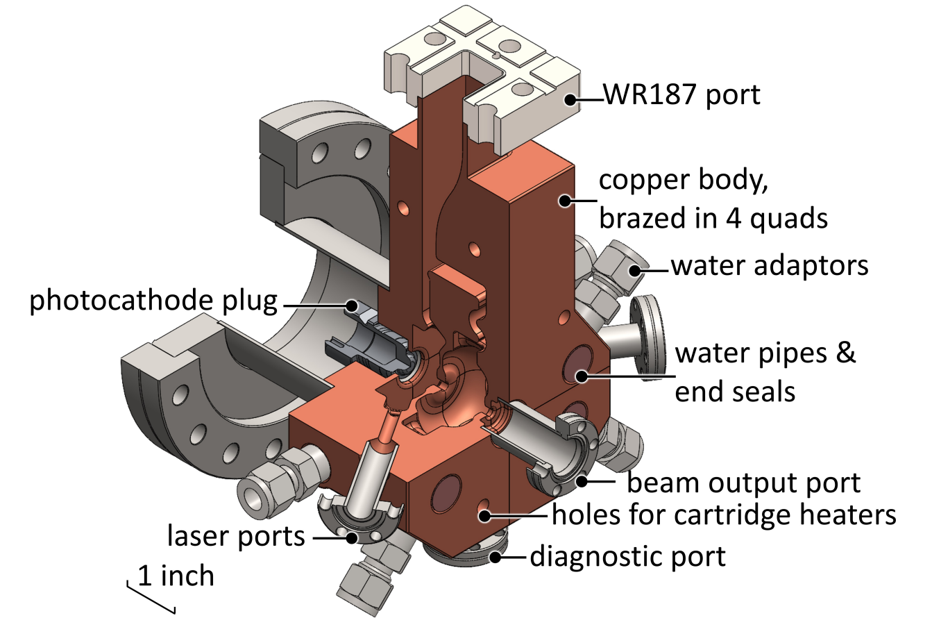
- 6-inch
Conflat flange interfaces with the photocathode and supports alignment
tooling.
- A WR187
waveguide supplies RF power to the cavity chain.
- Two mini-Conflat
laser ports are brazed to the cavity wall for photocathode
illumination.
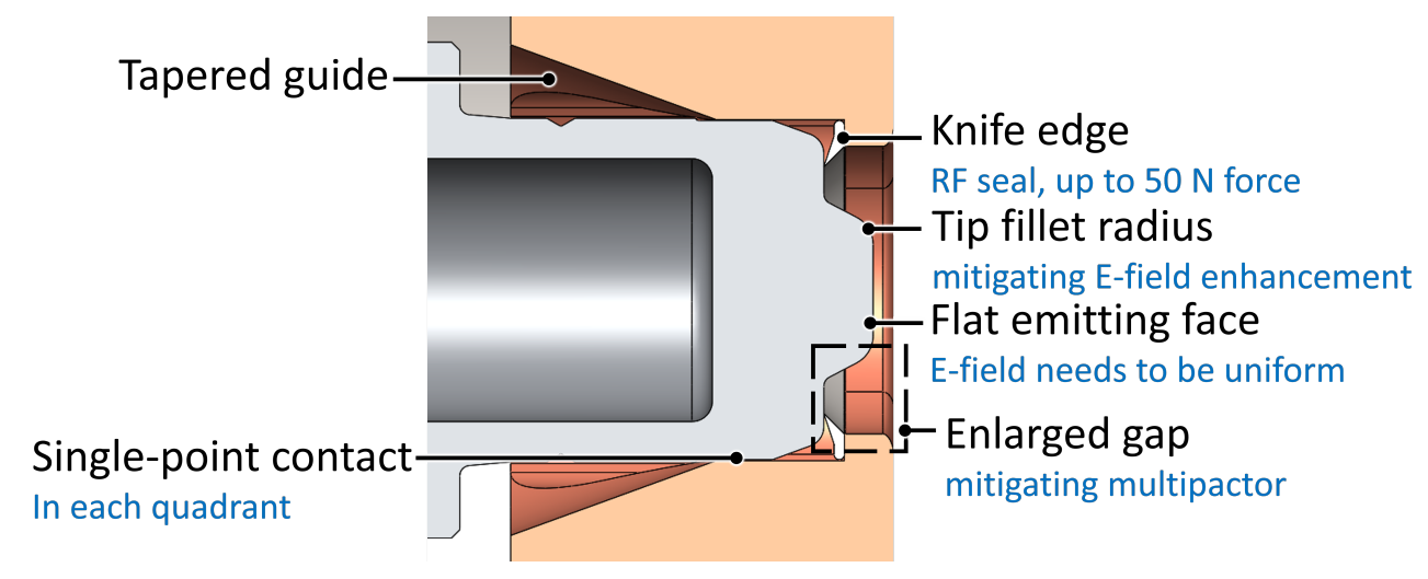
- A 304L
stainless-steel knife-edge supports longitudinal photocathode
positioning and was designed to withstand 50 N before yielding.
- The
photocathode plug includes:
- Field-minimizing
fillets
- A tapered
guide for centering without detuning
- A copper gap to prevent cavity-resonance distortion from cathode surfaces
- In the assembled configuration, the plug’s transverse alignment is defined by single-point contacts with each of the four copper quadrants.
- Revisions
improved the RF cell geometry and manufacturability across the
four-quadrant layout.
Assembly, Brazing, and Hardware Engineering
I led the development of all braze-ready hardware and
assembly methodologies, including:
- Iterated braze washer designs to maximize bonding surface area, promote full braze-material melting, enhance structural strength, eliminate void formation, and ensure long-term UHV-compatible sealing.
- Creation
of a complete braze hardware system composed of:
- Quadrant
braze joints
- Swagelok-based
water-cooling fittings
- Laser-input
port brazes
- Water
channel plugs
- Cathode-insertion
structural hardware
- Fixturing clamps and stability points for brazing cycles
- Conflat Flange attachments (inputs, outputs, and diagnostic ports)
- Detailed
alignment strategies ensuring quadrant coaxiality, minimal radial
deviation, and symmetric cavity formation.
- Full CMM
metrology and RCA validation of all key dimensions, alignments, and
assembly tolerances.
- Design
of cavity tuners enabling resonance adjustments.
- Development of the complete final assembly used for vacuum qualification and RF
testing.
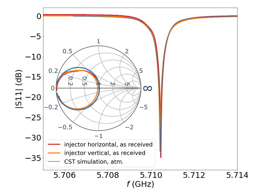
3. Low-Power RF Test Results
Low-power testing employed a bead-pull technique,
facilitated by a 0.7 mm hole drilled into the cavity to allow threading
of a nylon bead-pull line.
Key Findings
- Resonant frequencies closely matched CST simulations with minimal S11 reflection coefficents, demonstrating highly accurate machining, brazing, and material behavior.
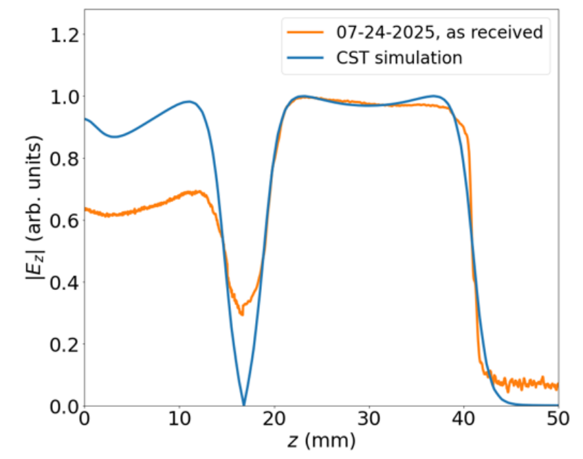
- Bead-pull
measurements revealed the cathode-region electric field amplitude was 32%
lower than simulation, consistent with expected losses and correctable
through tuner adjustments.
- The
measured RF phase advance between the cavity cells was 183°,
nearly identical to the 180° design target, confirming proper
coupling and quadrature symmetry.
These results validated the mechanical build quality and
confirmed that the Rev-2 cavity behaved as expected in the π-mode.
4. Conclusions
The successful design, fabrication, brazing, and low-power
testing of the 5.712 GHz RF photoinjector demonstrates the effectiveness of the
quadrant-based manufacturing process, tuner architecture, and alignment
methodologies. Despite moderate electric-field deviations near the
photocathode, the cavity met critical RF design requirements including
resonance, phase behavior, surface-field distribution, and coupling symmetry.
This project strengthened my experience in:
- Precision
RF-structure design
- Vacuum
and braze engineering
- Quadrant-based
fabrication
- Tuner
development
- CMM-based
tolerance validation
- RF–mechanical
integration from concept to prototype