

Overview
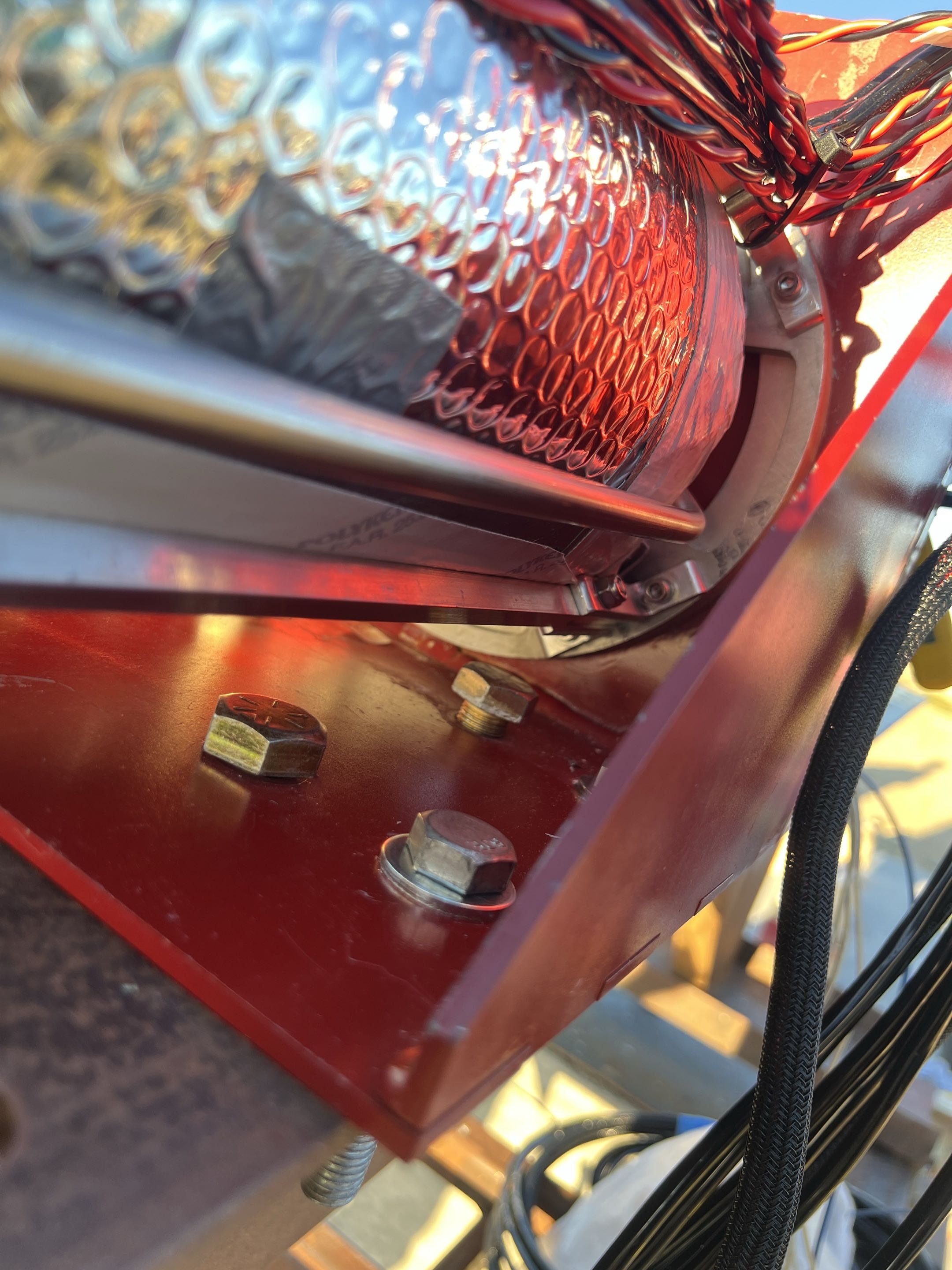
The Structures team was responsible for executing the full lifting and mounting operations required to transfer the rocket from the transport vehicle to the test stand and ultimately secure it to the I-beam for static fire. This involved coordinated manual lifting, alignment, and fastening of the system along with installation of lateral supports. Predefined lifting procedures, which were rehearsed through dry runs prior to the test, enabled smooth execution with no major issues during the handling phase. However, challenges arose during final fastening to the I-beam, primarily due to insufficient attention to structural interface details and incomplete interpretation of I-beam specifications.
Identifying DFA Issues
.png)
.png)
1. Interface Mismatch Between Test Stand and I-Beam
- A major issue arose from a mismatch between the test stand mounting hardware and the I-beam interface. The system was designed with 5/8” captive bolts, while the I-beam was configured for 1/2” hardware, resulting in an interference fit rather than the intended clearance fit. This required on-site modification of the I-beam (drilling and filing) to enable fastening.
- This issue highlighted a breakdown in design ownership and interface verification. After initial fabrication, the test stand no longer had a clearly defined responsible engineer to ensure continued compatibility with external systems. Additionally, late selection of the test site (Pad 2 vs. Pad 3) and limited early coordination with site operators contributed to incomplete interface definition.
2. Uncertainty in Vertical Placement on I-Beam
- Due to late decisions regarding which I-beam would be used, the team lacked predefined guidance on vertical placement of the test stand. This uncertainty impacted proper positioning of the igniter relative to the TCA and required multiple repositioning attempts.
- Combined with the need for on-site modifications, this extended what should have been a ~30-minute operation into a ~2-hour process.
3. Inefficient Lateral Support Installation
- The installation of lateral supports required repeated adjustments and real-time measurements due to a lack of predefined placement strategy. While not on the critical path, this introduced unnecessary inefficiency and increased setup time.
- The placement strategy was overly dependent on specific I-beam hole locations rather than being tied to the final test stand position, reducing adaptability when upstream decisions changed.
Proposed Design Changes (My contribution)


To address these issues, a series of design improvements were proposed and partially implemented, focusing on improving accessibility, modularity, and interface compatibility. (Full presentation linked to the left)
Key changes included:
1. Fastener & Hardware Redesign
- Replaced 5/8” captive bolts with 1/2” bolts and washers to match interface requirements and eliminate interference fits
- Reoriented bolt directions to allow removal without full disassembly
- Reduced reliance on captive hardware trapped by the assembled rocket
2. Improved Assembly Accessibility
- Identified critical hard-to-reach fastening locations
- Proposed adding side access slots to allow tool clearance and proper torque application
- Evaluated structural trade-offs of added cutouts, with plans for validation via analysis
3. Simplified Structural Interface
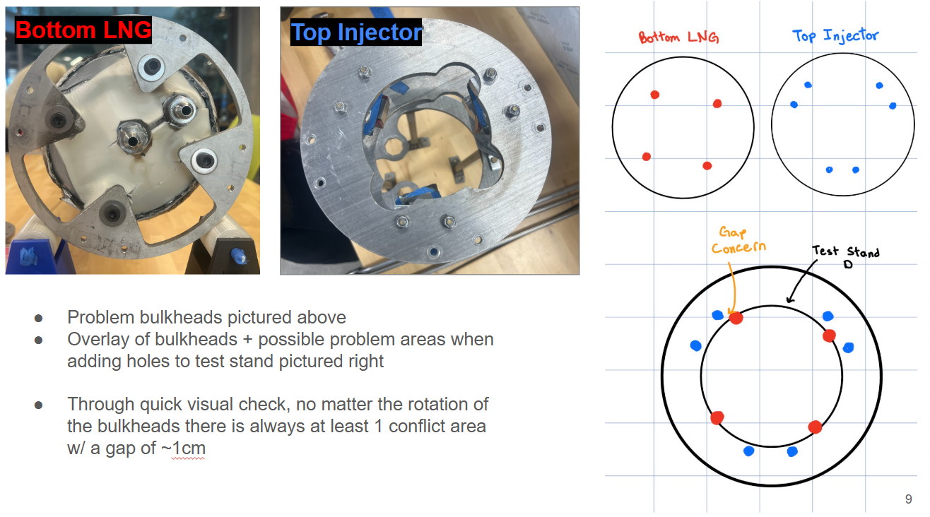
- Removed need for extra bulkheads used solely for bolt clearance, reducing unnecessary complexity
- Identified misalignment between LNG and injector bulkheads, creating gaps (~1 cm) regardless of orientation
- Proposed through-hole mounting design, allowing fasteners to pass directly through the test stand rather than relying on standoff spacing
Overall, these changes aim to reduce assembly time, improve reliability of fastening, and create a more robust and maintainable test stand for future static fire operations.