Problem Statement
Setting: Formula SAE testing is limited by track access and logistics, running the car requires safe space, clearance and mechanical readiness. To accelerate hardware and software development, we asked: what if we could "run" and test the car without ever putting it on the ground?
Challenge
The car’s core systems (powertrain, controls, telemetry) depend on live sensor data to function. Without valid IMU, wheel speed, steering signals and more, the software cannot be exercised, making off-car debugging nearly impossible.
What did I do?
Designed a 4-layer PCB sensor simulator with an STM32F4 and wrote transfer functions to model IMU, wheel speed, and steering angle outputs, generating realistic signals so the car’s powertrain, controls, and telemetry software could be exercised entirely off-vehicle.
System Conception
For the system to work, three Validation Sensor Simulators are required. Two of them output signals to the car's Front and Rear sensor module, which collects the data, packets them and sends data to the car's vehicle controller where decisions (safe to run?) are made. The third Validation Sensor Simulator is connected to the Vehicle Controller where we can read and process CANBUS data packets are observe if the vehicle is running as expected via an internal program Chimera. 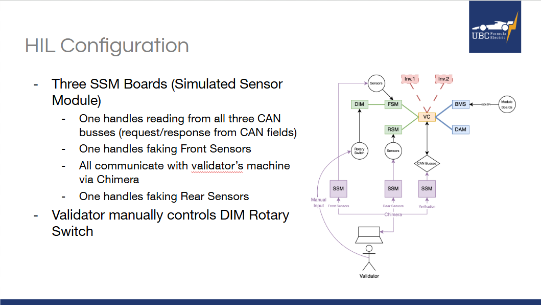
Hardware Layout Conception
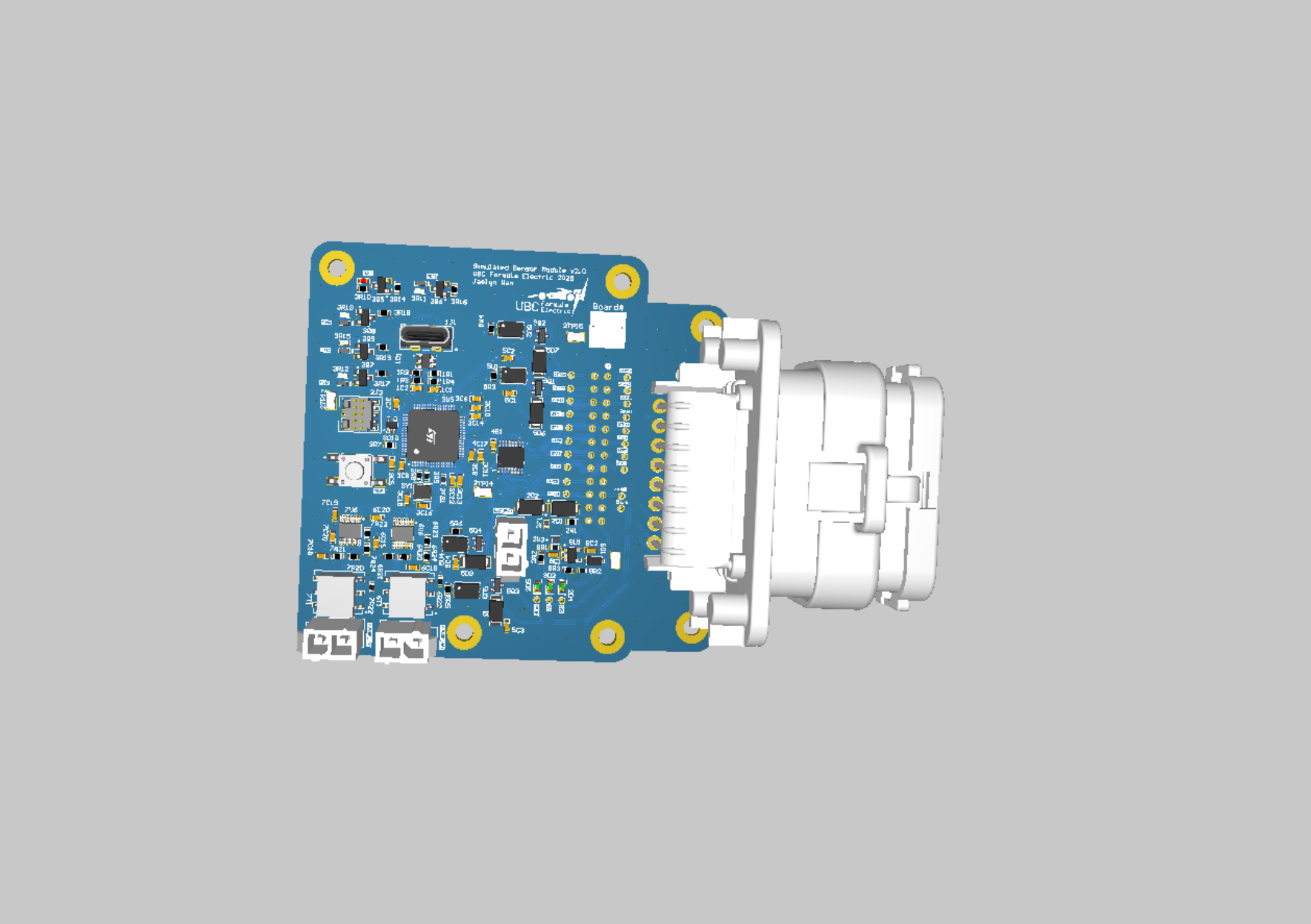
The system uses a reusable smart microcontroller board paired with a simple routing board, allowing the same core design to be applied across different hardware setups.

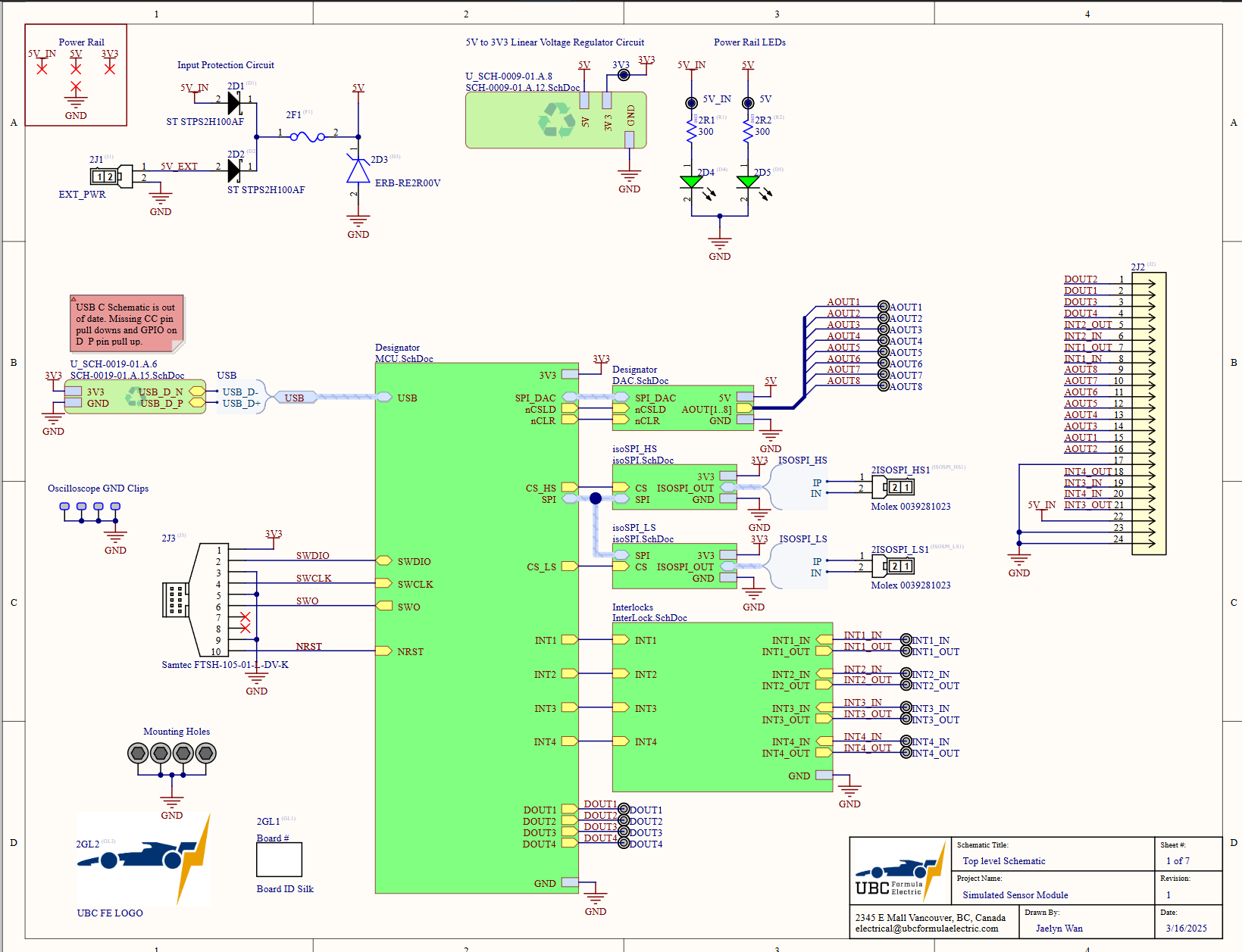
Hardware Schematics
Top Level Schematic
MCU Schematic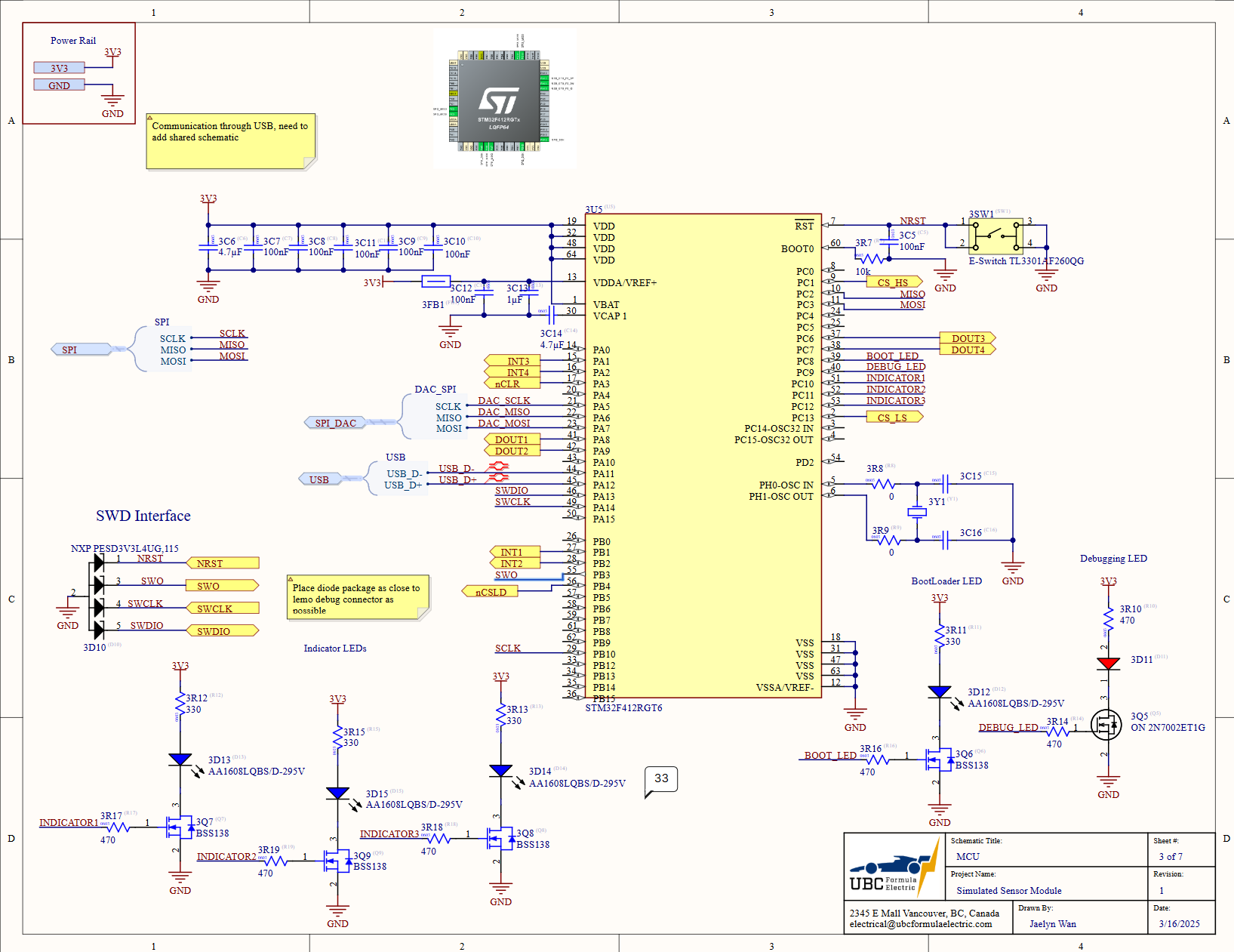
For entire schematic: Link
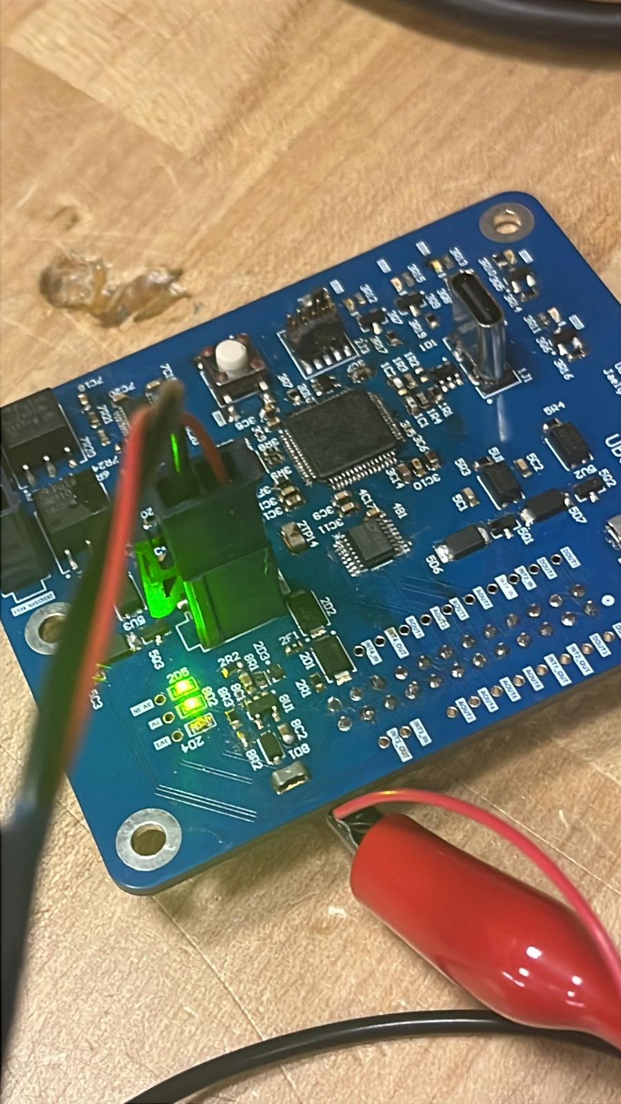
Final Product