


Project Background
Shortly after I started working at WIC, I got to work on the new bolted system project at the company. This project was started to reduce the number of parts that would need to be designed and drafted across the WIC portfolio. When I first started this project, I mostly worked on drafting the parts, using GD&T and best drafting practices to ensure that the WIC shop would be able to fabricate the parts easily, and incorporating feedback from them as needed. As I gained more experience at the company, I transitioned into designing parts that could be useful as a standard, as well as testing their fit and function, including running FEA simulations, hand calculations, and creating prototypes in collaboration with the shop. I have worked on many different parts and projects, but here I will showcase the highlights of one project that I feel best encapsulates the work I have done throughout this project, the development of a new standard hanging conveyor support system.
Problem Statement
I worked on a USPS project with very complicated existing conditions that necessitated hanging the conveyor systems rather than the floor supported systems WIC typically uses for projects. As a result, I was tasked with creating a support system that could be used for all of the conveyor in this project, as well as any future USPS projects. The supports must meet the following criteria:
- Must be usable for 36" and 42" conveyor widths
- Must be able to withstand the highest seismic forces in the United States
- Must be able to support conveyor from 40" to 260" below the ceiling
- Must be able to withstand the loading conditions of all USPS projects
- Must be able to attach to the conveyor at any point to account for the buildings existing conditions
Design
Based on shop capabilities and installation concerns, it made sense to start the design as angle supports connected to a pipe sill with cross bracing as needed. There was a similar setup that had been used for other projects, so this was a good starting point for the design. Making the first design was simple enough, but I needed to be sure that the supports would have enough bracing to withstand the forces on the conveyor, as well as any seismic forces that may arise. To test the extremes of the supports, I mapped out the geometry to determine where bracing could be placed while accounting for package clearance. From here I tested three scenarios, the longest angles with no cross bracing, one set of cross braces, and two sets of cross bracing. To test these configurations in Inventor, I used both the frame generator simulation and FEA simulations as shown in the figures below.

Figure 1: Frame Generator Seismic Displacement Analyis
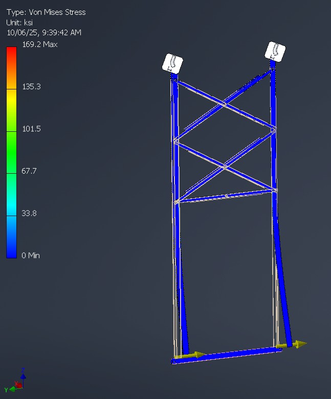
Figure 2: FEA Simulation of Supports
Once the simulations were set up, I was able to select the member sizes and cross bracing that would satisfy our conditions. Once the support selections were solidified, the next step was to create a system that could locate the supports at any point along the conveyor. To satify this condition, I made 3 designs and had the shop fabricate a prototype of all 3 as shown below.
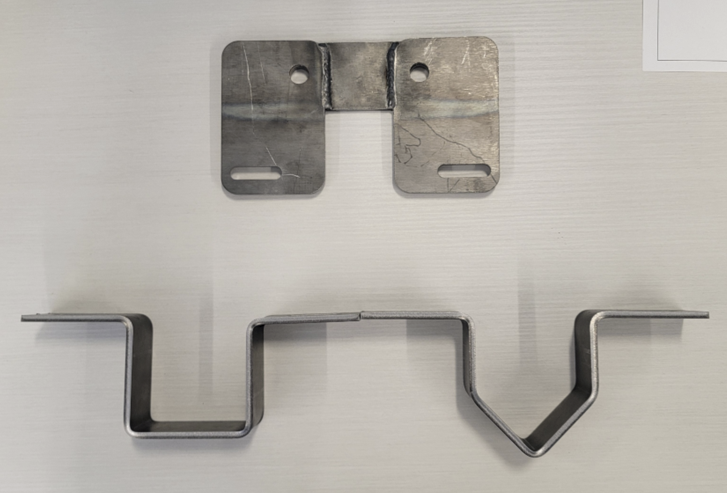
Figure 3: Three Designs for Hanging Support Joints
After making the three prototypes, the shop recommended the bottom left design for ease of manufacturing, so after verifying via FEA and hand calculations that the design could withstand the forces on the conveyor, I implemented that design into the overall solution.
Conclusion
Taking into account all of the design testing, the final design was selected as shown in the picture below.

Figure 4: Setup of Final Hanging Conveyor Support
This solution was drafted to be able to be fabricated for any USPS projects that use hanging supports, and a standard models were created to easily integrate into any layouts where they were needed. These parts were implemented into postal facilites, and have help up to the standards of both WIC and USPS. These parts will continue to be used as a part of the WIC portfolio moving forward.