


Problem Statement
The primary goal of this project was to develop a 3D printed prosthetic foot capable of supporting a child with a trans-tibial amputation or deformity (below the knee). The team’s role was to create a 3D prosthetic limb for trans-tibial amputations consisting of the foot and its connection to a pylon. The team’s scope of the project was specified to create a foot that can support the weight of an 80-pound child over the course of two years and can be easily 3D printed with readily available filaments. The model must also be open source and include an instruction manual, so that anyone with a capable printer will be able to make this prosthetic. Lastly, the product should be a passive device, not utilizing any electronic control, to decrease cost as well as simplify the ease of device production.
Design
Three designs were created based on the criteria outlined for the project. The designs are shown in the figures below, with the motivations for each design as follows. Design 1 is the high load model, made to efficiently bear the weight of the user, while still fitting in the user’s shoe if desired. Design 2 is the anatomically correct foot designed with the intent of not being recognized as a prosthetic. Finally, Design 3 is a flex ankle design that would have a flexible hinge and the joint between the ankle and shin.
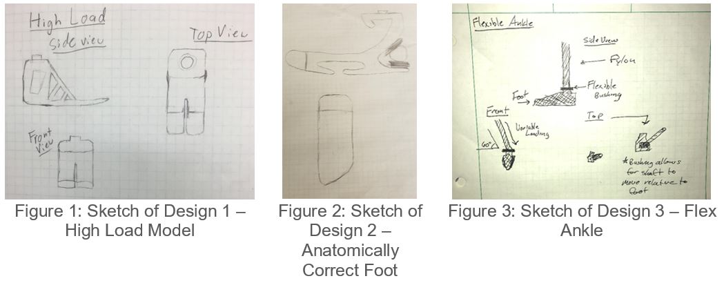
After reviewing the 3 designs, the High Load design, Design 1, was deemed the best fit for our design criteria. It’s simple and effective design makes it ideal for the open-source hardware application outlined in our project goals. In addition, the selected design was the most stable, and able to handle the most load from the patient. This results in a simple and effective design with little post-print processing. However, the selected design is not tailorable to the cosmetic needs of the patient and did not resemble an actual foot. To bring this aspect into our design, we have decided to modify the High Load design to be able to fit within a shoe. This allows for the product to be as stable as possible, while giving the patient the option to place the prototype in a shoe.
Testing
The design was tested thoroughly with both FEA in SolidWorks and physical testing to ensure that the design would satisfy the needs of the user and met all of the criteria defined for the project. The Figures below show the Factor of Safety plots for the two load scenarios. Figure 4 shows the balanced load with half of the force on the rear and half on the toe. Figure 5 shows the load concentrated at the toe. The scenario with a full load on the back was not consider in the FEA because the back is very thick and not an area of concern. As shown in Figures 4 and 5, both FOS are above 2, so the part passed our virtual test setup.
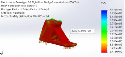
Figure 4: FOS Plot of Balanced Load
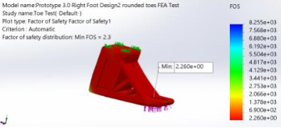
Figure 5: FOS Plot of Toe Load
3D printed materials are built layer by layer and are therefore difficult to model in software because they do not perform like a solid piece of material. Due to this, a higher importance was placed on the performance of the feet under physical testing. Testing of the foot was started by attaching it to a walking boot. The boot was used to walk, run and jump under the weight of an adult. The walking boot test setup is shown in the figures below.
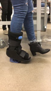
Figure 6: Walk Testing Foot in Boot
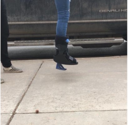
Figure 7: Jump Testing in Boot
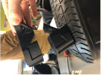
Figure 8: Failure of Foot in Boot Testing
After we were able to print a part that could withstand the walking boot tests we put it through, we moved on to testing the foot with a hydraulic press to failure. The setup for this procedure is as shown in Figure 9, with the results shown in Figure 10.
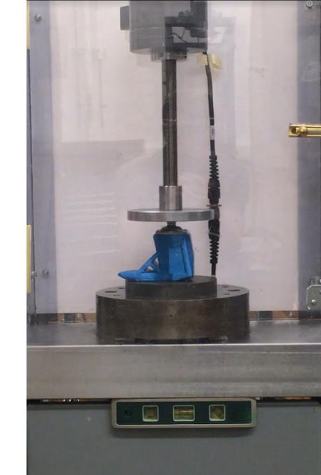
Figure 9: Load Frame Setup
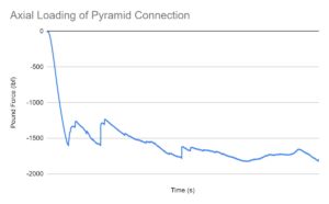
Figure 13: Axial Load of Pyramid Connection
Conclusion
After running tests on the final design of the foot, we determined that the foot can hold a weight of up to 120 lbs, but we did not have time to factor in fatigue testing to this number. If given more time, that would be the next set of tests to ensure that this weight could be sustained over the 2 years we set out to reach in our goal. However, the design did meet the rest of our goals, as the foot could be fit in many children's shoes, could be easily printed on a entry level 3D printer, and cost roughly $50 to fabricate. While we were happy to meet the goals that we could, the project was unfortunately cut short before we could certify that the design met all of our original goals.