


Problem:
The 2025 First Robotics Competition endgame requires robot to hang onto a designated climbing structure(called cage) and be off the ground until after the end of the match to score endgame points and ranking points.
Climbing structure
Cage
Design Objectives/Requirements
These are the requirements that are set by me and the design team and of which the final design of the system must meet:
- Fast climb time - sub 3s, to allow more time to do other game tasks
- Must be able to be quickly stowed and deployed in endgame
- System must reduce required driver input and possibly error when attempting to climb
- Securely lock onto the cage once it is in contact with the climber
- Prevent the robot from falling once climbed
- Reliably climb at the end of every match without damaging the system
Initial Concepts & Prototyping
Going back to the design requirements, there are two that can be prototype and tested: Fast climb time and securely locking the cage.
Fast climb time
The main way to have a fast climb time is to reduce the amount of input and error that the driver can make. In other words, I wanted the system to help the driver align to the cage and all they have to do is move the robot straight forward, and the system would intake the cage and locks onto it. For these reasons, the prototypes were all designed to have a motor powering wheels to intake the cage structure. The difference between the prototypes' intake would be whether the system would engage with only one side/pole or two sides/poles and wheel materials
Securely locking the cage
This requirement is fairly basic and to reduce complexity of the final design, we would test different types of spring-loaded latch in the prototypes.
Prototype testing variables
- Intaking 1 side/pole vs 2 sides/poles
- Different wheel durometers
- Different types of latches
Prototype V1
- Intake 2 side of the cage
- basic one way latch
What worked:
- Were able to intake and locks onto cage though not consistently
- requires a certain cage orientation to work
What didn't work:
- If cage is at an odd angle(like below), the cage would just bounce off the system and to the side

- the latch barely covers the cage and doesn't seem secure
Prototype V2
- Most of the system is the same as V1
- Added funnels to the side to maybe help guide the cage better
- Added a kicker wheel in the middle
- the idea is that when the cage is at an off angle, the kicker wheel will reorient it
What worked
- Slightly better consistency with intaking and locking onto the cage than V1
- able to intake 1 side of the cage even if the cage is not in the right orientation
What didn't work
- The middle kicker wheel sometimes bounces the cage off the system
- Still can't intake both sides of the cage
Prototype V3
- Only intaking and locking onto one side of the cage
- added a small funnel
What worked
- Consistently intake and locks the cage as long as the cage hit the funnel
- Intake and locks any orientation of the cage
- Doesn't bounce the cage away
What didn't work
- Funnel was too small and needs to be bigger
- The latch still doesn't cover much of the pole, need a better design
Prototyping Conclusions
- Final design will be intaking and locking only 1 side of the cage
- Reasoning - most consistent in all of testing
- Funnel in the final design needs to be bigger and have a wider angle
- Reasoning - assist drivers and reduce alignment issues
- Needs a better latch mechanism
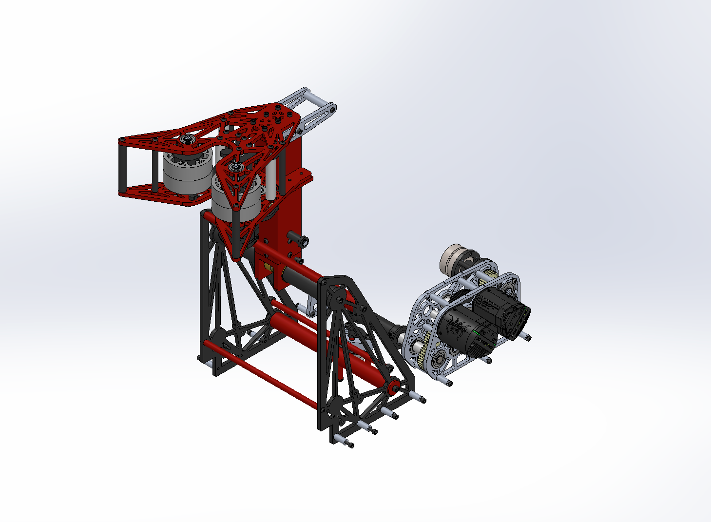
Final Design
Climber intake
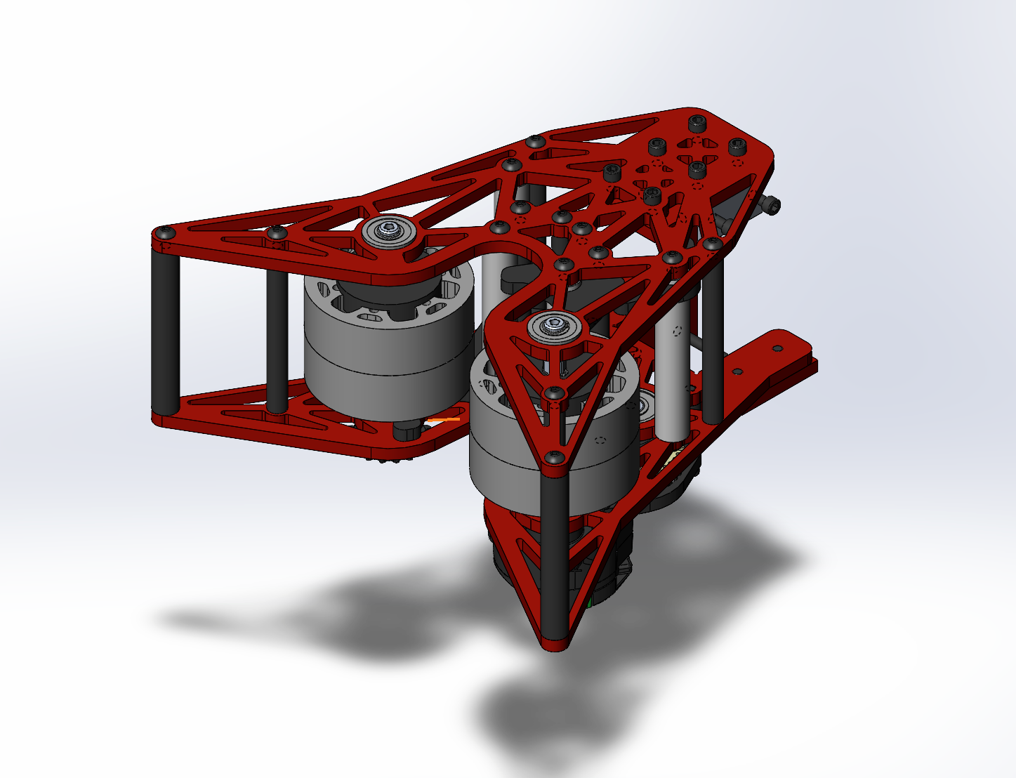
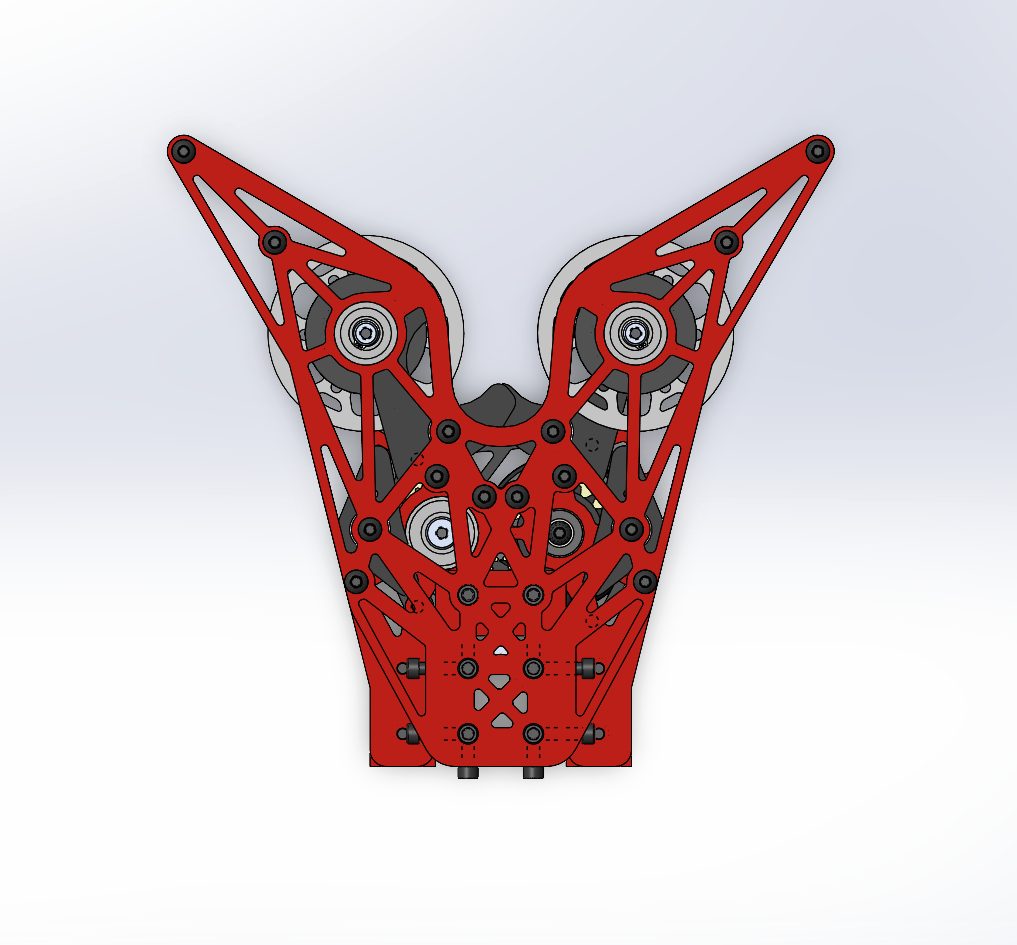
What changed from prototyping:
- wider funnel
- new latch mechanism inspired by car door latch
- I chose to implement this kind of latch mechanism for two reasons:
- it allows for full coverage of the cage side when it is locked in, meaning there are no possible chance that the cage can slip out
- The latch mechanism turns the intake into an entirely mechanical system, meaning that it could still work even without the motor powering the intake wheels, as the cage is what trigger the latch and the latch helps brings the cage in while at the same time, the cage is bringing the latch in.
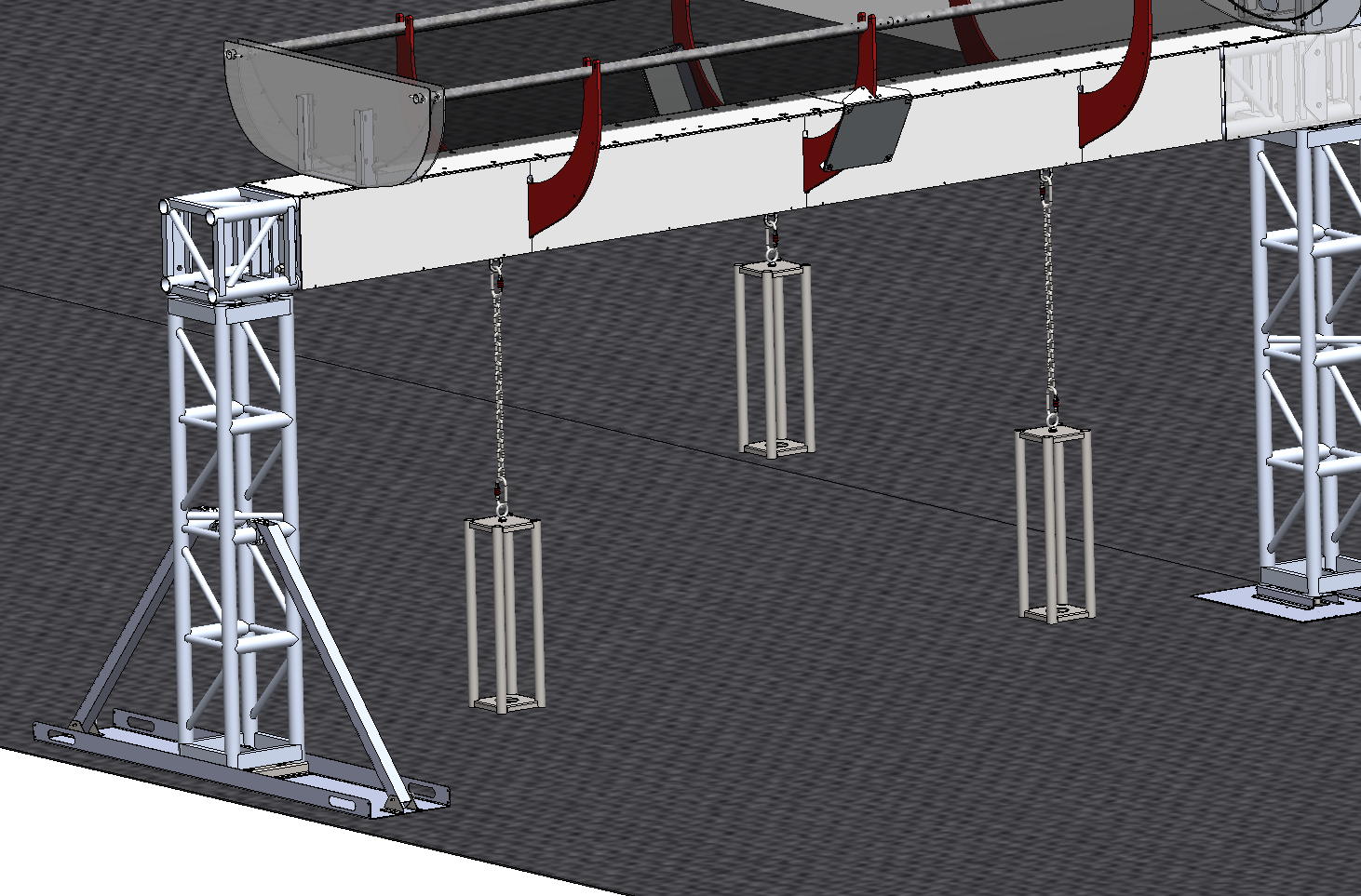
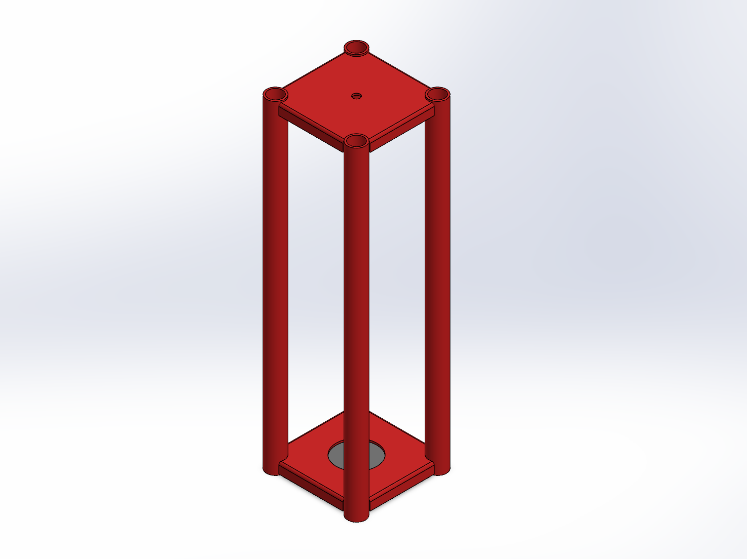
Climber structure
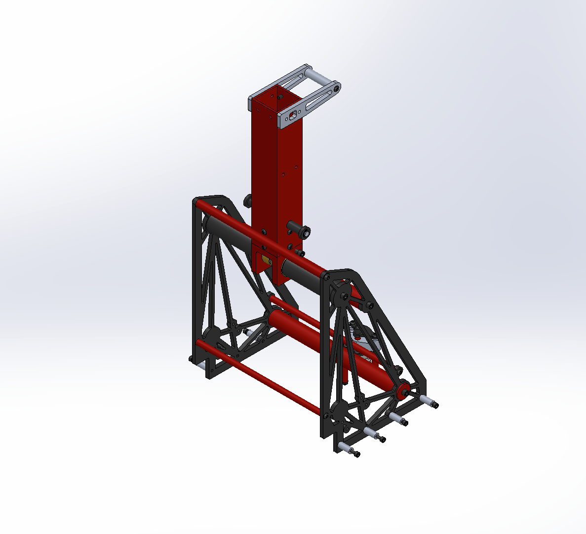
- The climber intake mounts to the top of the arm
- The entire climber structure mounts to the chassis of the robot
- Quick deploy system in the back
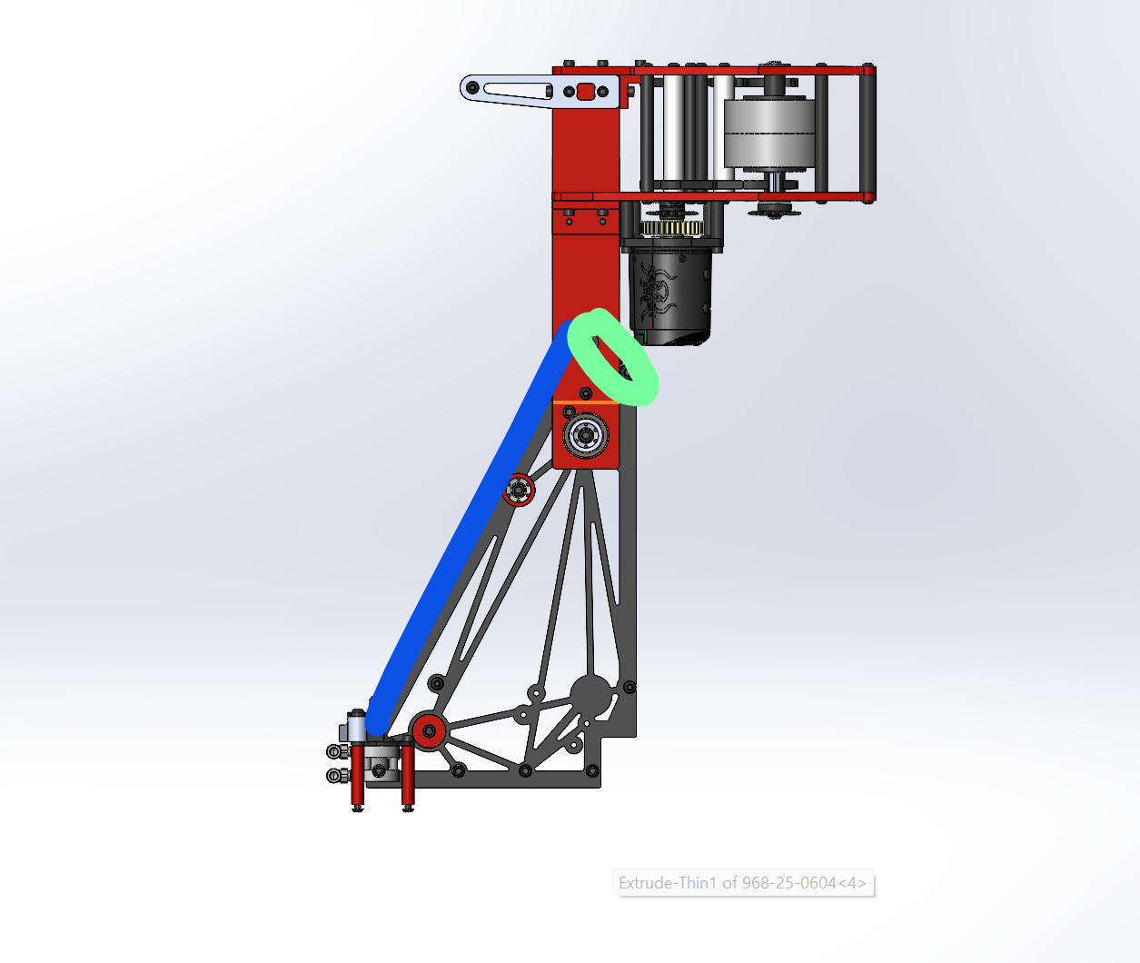
- A short 1/8" od rope is connected to the arm
- the rope has a small hole tied at the other end which allows for the piston stroke to pass through it. The piston then pass through a top plate which prevents the rope from slipping out of the stroke
- The arm is also spring loaded to the front of the structure
- When the piston stroke goes up and passes through the top plate, there is no gap for the string to go through, therefore locking the arm in the stowed position
- When the piston stroke goes down, there is a small gap just enough for the string to pass through, releasing the climber arm from the lock, allowing it to be spring deployed quickly
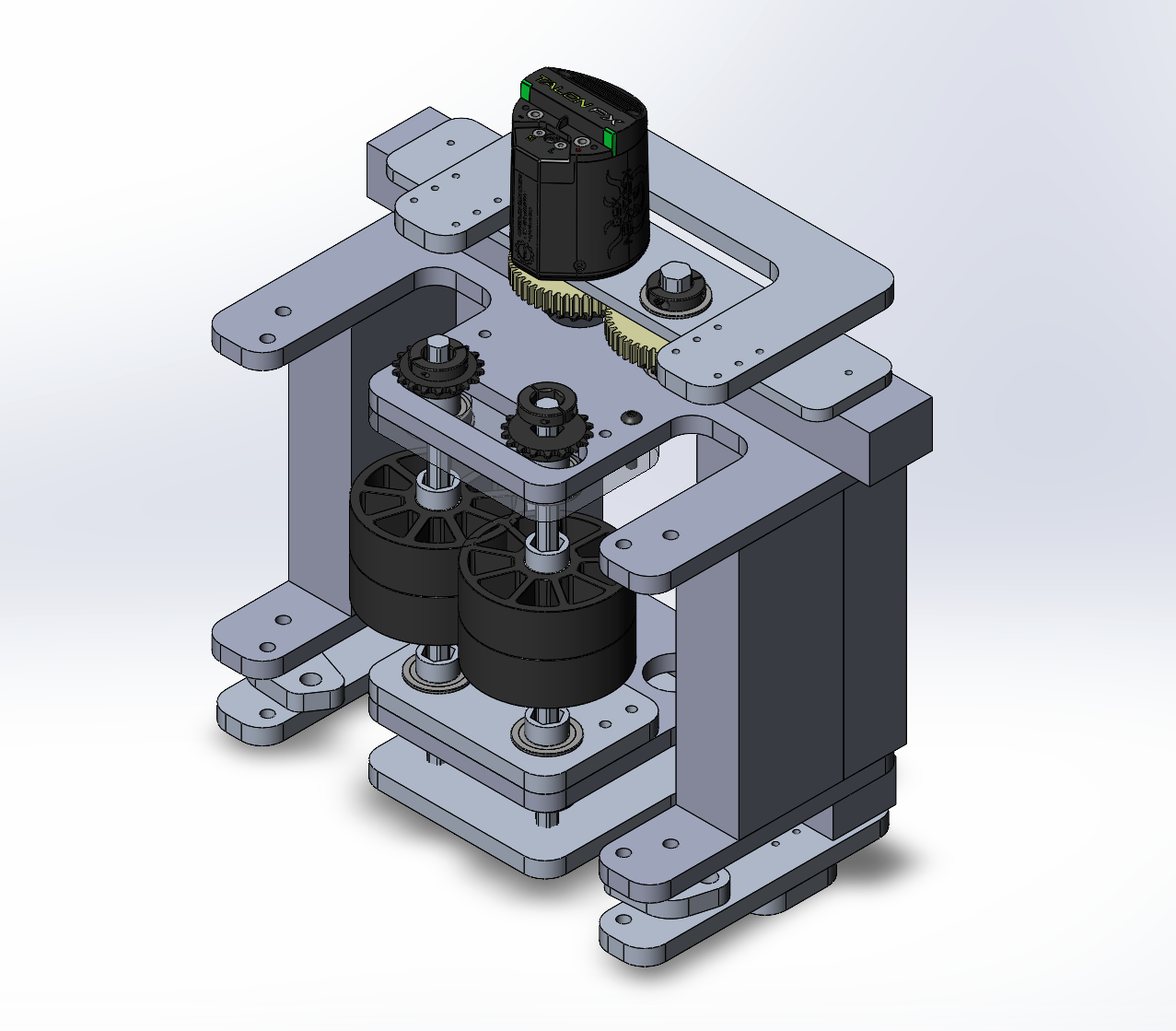
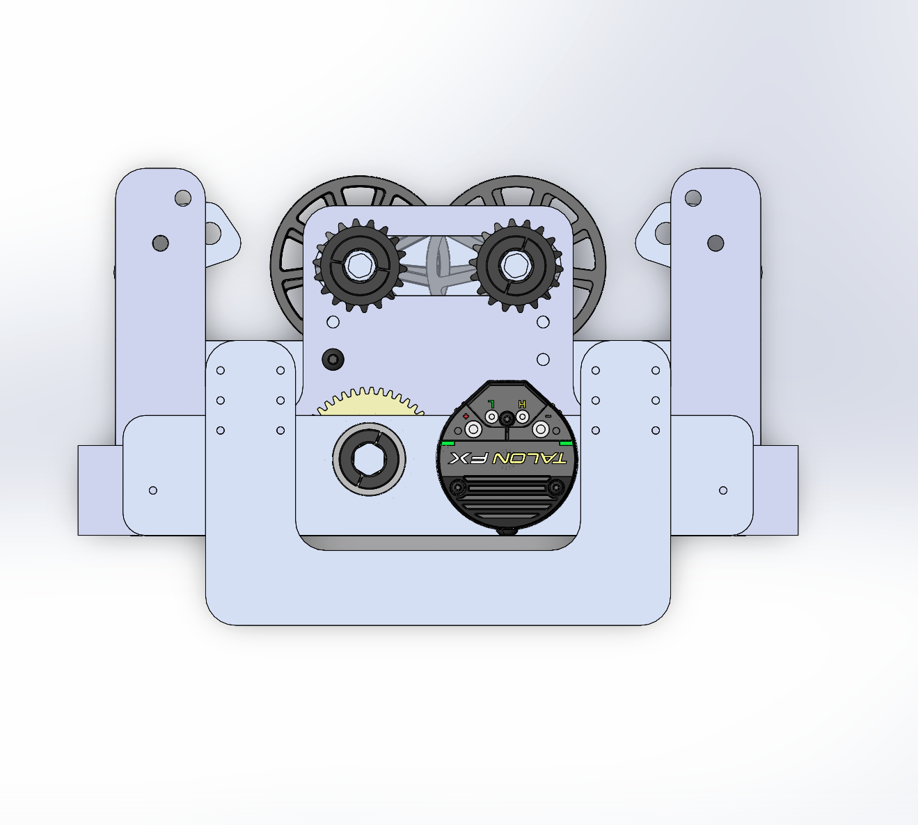
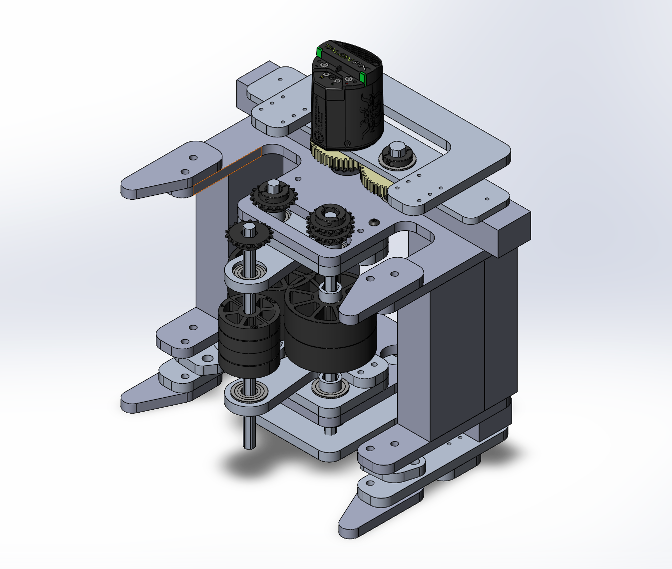
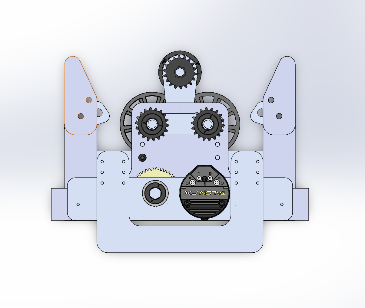
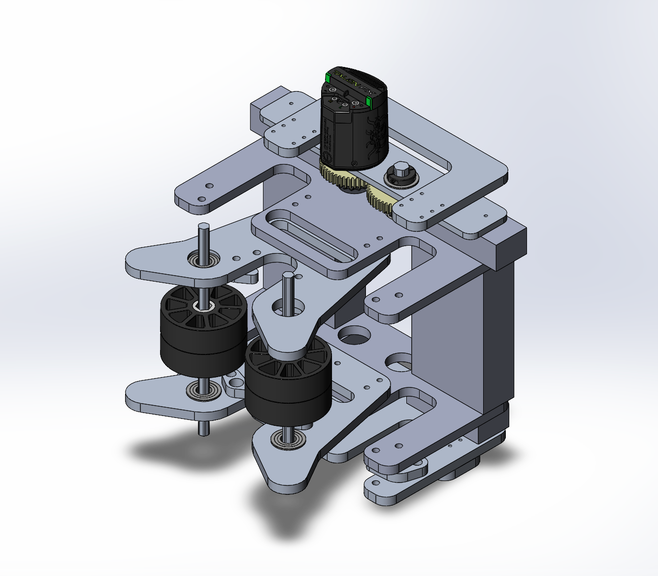
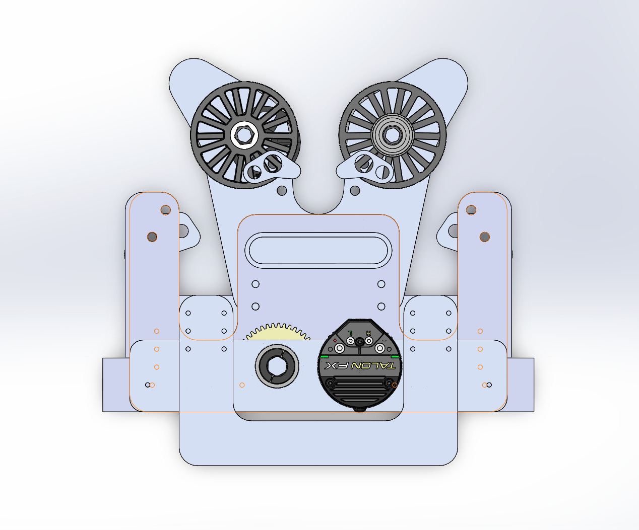
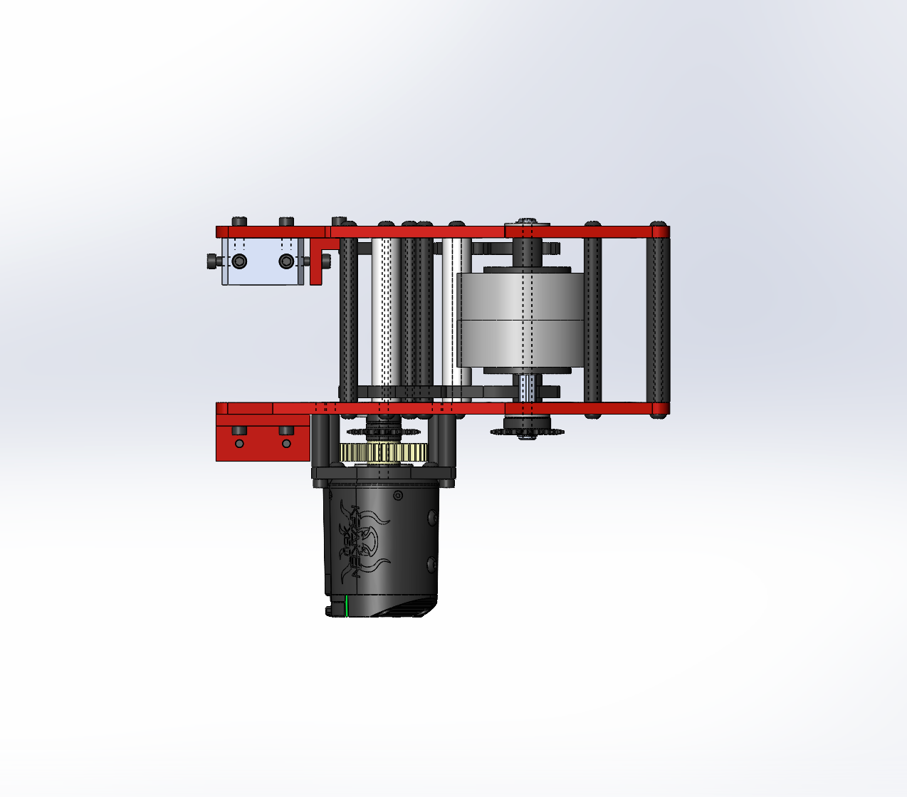
Winch Gearbox
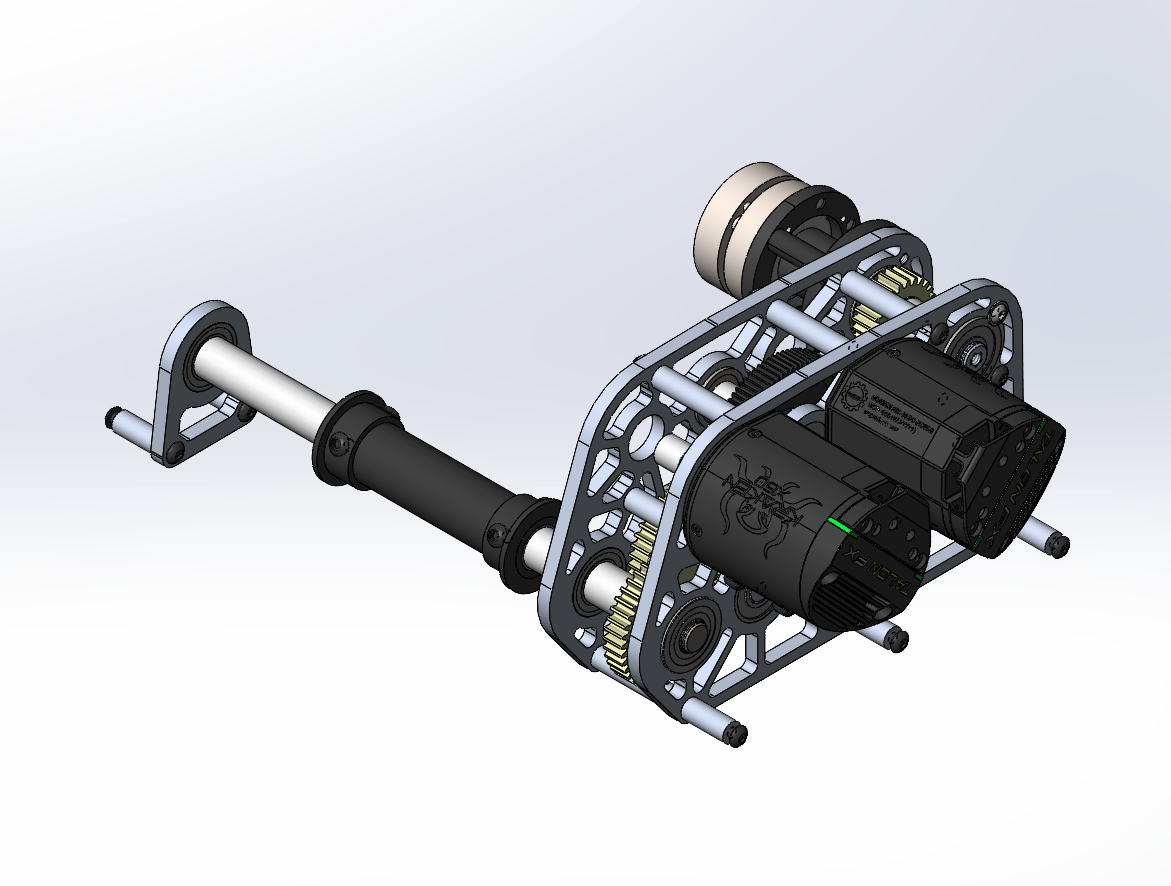
- Powered by two motors
- 70:1 gear ratio
- Air brake to prevent the climber arm from moving after the match(motors loses power at the end of the match and the gear ratio are quite high enough to prevent the gearbox from being back driven)
Final Result
Note: this is a test run so the speed of the climb is not as fast as it would be at competition