


Problem Statement
Professional robotic camera arms used in cinematography are precise but extremely expensive, heavy, and complex, making them inaccessible to independent filmmakers and advanced hobbyists. The market lacks a solution that balances affordability, portability, and professional motion quality. Our goal was to design a low-cost, user-friendly, high-precision robotic camera arm capable of delivering smooth cinematic motion in small studio environments.
Engineering Specification
The engineering specifications were derived from the comprehensive market and competitor research, as well as from additional calculations.
| Specification | Metric |
| Payload | ≥ 1.0 kg at full horizontal reach |
| Radial Reach | ≥ 0.7 m, height ≥ 1.0 m |
| End-effector speed | ≥ 0.7 m/s (jerk-limited) |
| Camera acceleration | ≥ 1.0 m/s² |
| Path repeatability |
≤ ±5 mm over 1 m |
| Arm-only mass |
≤ 20 kg; arm + track ≤ 45 kg |
| Assembly time |
≤ 8 hours |
| Arm-only Bill of Materials |
≤ CAD $8,000 |
Candidate Designs
Three candidate designs were derived and considered from over 30 initially iterated ideas during the developmental process.
Candidate 1
The first candidate design prioritizes precision and stability. A semi-stationary tripod base supports four joints, and a total of 5 degrees of freedom (DOF). The entire system can be powered using a standard electrical outlet.

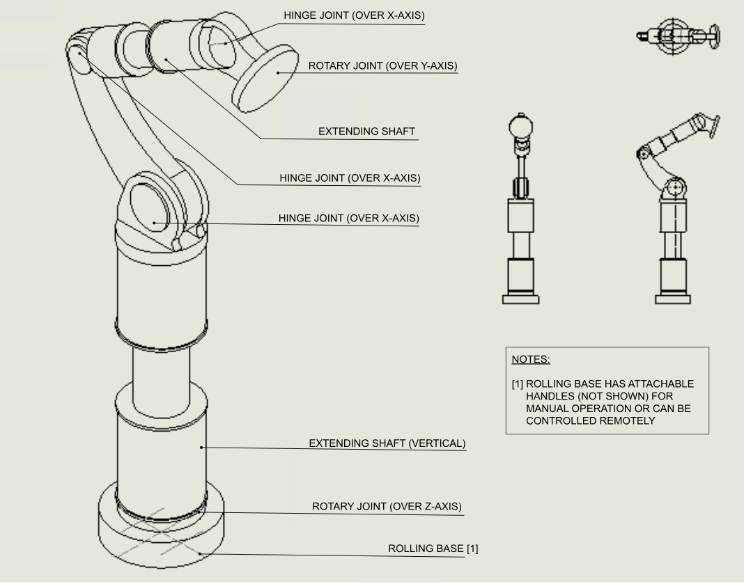
Candidate 2
The second candidate design uses remote controlled rolling base to allow movement in the horizontal plane and an extending shaft for vertical translation in addition to rotation over all 3 cardinal axes.
Candidate 3
The third candidate design maximizes DOF through the use of a remote-controlled sliding track that allows movement in the horizontal plane in addition to hinge over all 3 cardinal axes. The design has 5 joints. 
Final Design Selection
Using the Pugh Matrix, we then evaluated our candidate designs.
Component | Candidate 1 | Candidate 2 | Candidate 3 |
Base | 1 | 2 | 0 |
Arm | 2 | 0 | 1 |
End-Effector | 2 | 1 | 0 |
Final Design | Arm + End Effector | Base | - |
Proposed Final Design
Our team designed a hybrid 6-DOF robotic camera arm mounted on a belt-driven sliding track, combining:
- 5 rotational joints + 1 prismatic axis
- Carbon-fibre arm links for high stiffness-to-weight performance
- Aluminum sliding track for stability and precision
- Geared brushless DC and closed-loop stepper motors
- 2-DOF pan-tilt end effector with ARCA-Swiss quick-release mounting
This configuration enables high-speed linear tracking shots, precise framing control, and repeatable motion capture in small studio environment.


Performance Validation
The final design exceeded all major performance targets:
- Path repeatability: ≈ 0.105 mm (far better than ±5 mm requirement)
- End-effector speed: ≈ 1.42 m/s
- Camera acceleration: ≈ 1.5 m/s²
- Arm-only mass: 17.06 kg
- Total system mass: 44.37 kg
- BOM: ≈ CAD $5,554
These results confirm that the design meets all the engineering specifications and achieves professional-level motion performance at a lower cost than competitors.
My Individual Contributions
Within the team, my primary responsibilities included:
- Performing motor torque, speed, and gearbox ratio calculations
- Conducting repeatability, end-effector speed, and camera acceleration analysis
- Completing mass properties and material selection using SolidWorks
- Supporting candidate design comparison and Pugh Matrix evaluation
- Contributing to the final CAD assembly and system integration
Teamwork & Project Management
My team used a structured engineering design workflow, including:
- Multi-stage concept generation → refinement → final hybrid selection
- Task scheduling with a team Gantt chart
- Weekly technical progress meetings
- Subsystem-level responsibility division across the team
The experience strengthened my ability to collaborate on complex mechanical systems, communicate design intent through visuals and calculations, and integrate multiple subsystems into a coherent final design.
Conclusion
I developed skills in system modelling, motor control, precision motion, and performance validation, which directly translate to my interest in robotics and ML-driven physical systems. Most importantly, it taught me how to bridge real-world constraints and specifications to build deployable engineering solutions.