


Project Overview
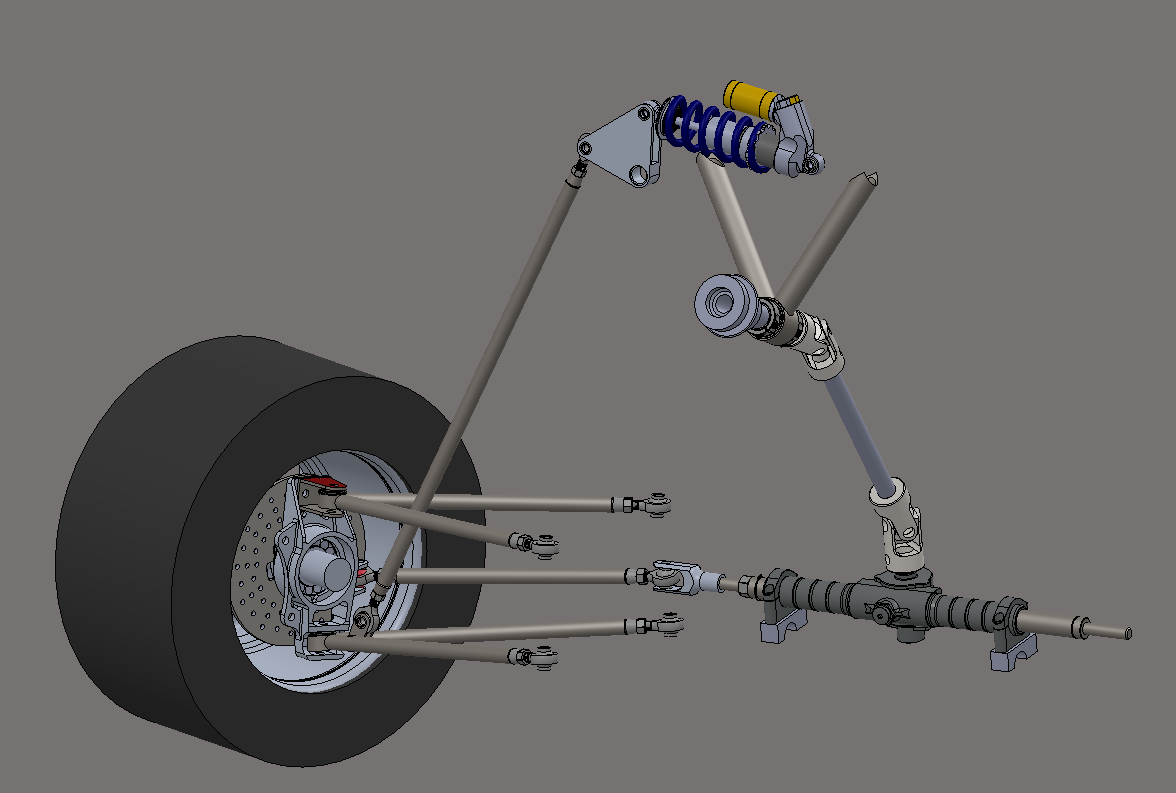
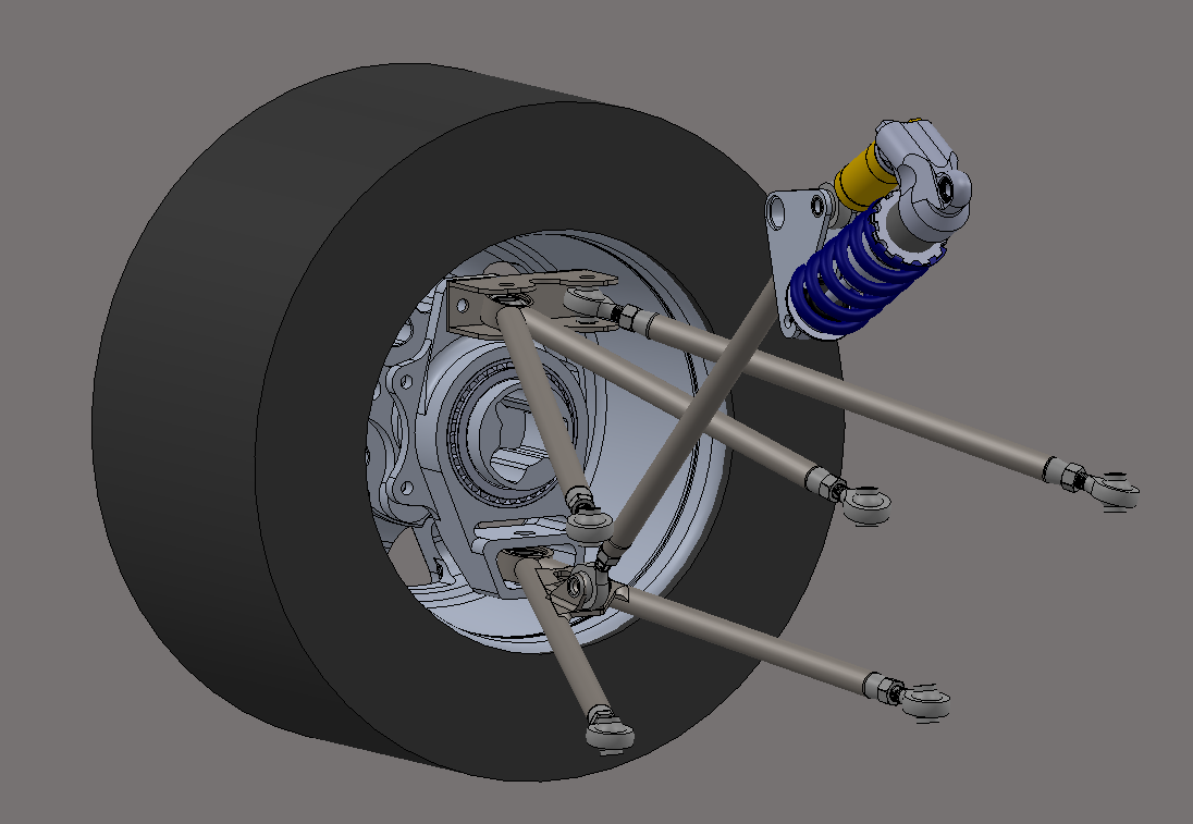
I led the design of the suspension system for NYU’s Formula SAE Electric vehicle, owning the geometry, packaging, and structural validation of a double-wishbone architecture. I designed control arms, uprights, rockers, pushrods, and shock mounts using parametric CAD, and validated critical components with hand calculations and FEA. My work emphasized achieving predictable vehicle dynamics, minimizing weight, and ensuring clean integration with the chassis, brakes, and powertrain systems.
System Requirements
The suspension was engineered to meet key performance goals, including targeted roll center heights, optimized camber gain, reduced scrub radius, and controlled toe curves during steering and bump events. Additional requirements included minimizing unsprung mass, supporting high cornering and braking loads with adequate safety factors, and packaging all components around chassis, battery, and inverter constraints while remaining manufacturable with available processes.
Bill of Materials (BOM)
The following table lists the components used in the prototype, including part numbers, quantities, materials, estimated costs, and potential suppliers.
Item | Component | Part Number | Qty | Material | Cost ($) | Supplier | Notes |
1 | Heat Sink | 637-20ABPE | 1 | Aluminum | 25.00 | McMaster-Carr | 100x100x50 mm, extruded aluminum |
2 | Cooling Fan (12V, 40 mm) | AFB0412SHB | 1 | Plastic/Metal | 10.00 | DigiKey | Low-noise, 35 dB max, 12V DC |
3 | Device Housing | Custom (3D-printed) | 1 | PLA | 15.00 | University 3D Print Lab | FDM-printed, 200x150x100 mm |
4 | Thermal Insulation Foam | 851-074 | 0.5 m² | Polyurethane Foam | 8.00 | Amazon | Cut to fit optics compartment |
5 | Temperature Sensor | DS18B20 | 1 | N/A | 12.00 | Adafruit | ±0.5°C accuracy, digital output |
6 | Arduino Uno | A000066 | 1 | N/A | 25.00 | Arduino Store | Runs Python PID via serial interface |
7 | Fan Muffler | Custom (3D-printed) | 1 | PLA | 5.00 | University 3D Print Lab | Reduces fan noise |
8 | Fasteners (Screws, M3) | 91292A112 | 10 | Stainless Steel | 3.00 | McMaster-Carr | M3x10 mm, for securing components |
9 | Thermal Paste | AS5-3.5G | 1 | Silicone-based | 5.00 | Amazon | Improves heat transfer to sink |
Motor Review
Basic PID Controller Script
PYTHONimport time

class PIDController:
    """A PID controller for precise control in robotic systems.

    Attributes:
        kp (float): Proportional gain.
        ki (float): Integral gain.
        kd (float): Derivative gain.
        setpoint (float): Desired target value.
        prev_error (float): Previous error for derivative calculation.
        integral (float): Accumulated integral term.
        dt (float): Time step in seconds.
    """

    def __init__(self, kp: float, ki: float, kd: float, setpoint: float = 0.0):
        """Initialize PID controller with gains and setpoint.

        Args:
            kp: Proportional gain for error response.
            ki: Integral gain for accumulated error.
            kd: Derivative gain for error rate of change.
            setpoint: Desired target value (default: 0.0).
        """
        self.kp = kp
        self.ki = ki
        self.kd = kd
        self.setpoint = setpoint
        self.prev_error = 0.0
        self.integral = 0.0
        self.dt = 0.01

    def compute(self, current_value: float) -> float:
        """Compute PID output based on current system value.

        Args:
            current_value: Current measured value of the system.

        Returns:
            float: Control signal to adjust the system.
        """
        # Calculate error
        error = self.setpoint - current_value

        # Proportional term
        p_term = self.kp * error

        # Integral term
        self.integral += error * self.dt
        i_term = self.ki * self.integral

        # Derivative term
        derivative = (error - self.prev_error) / self.dt
        d_term = self.kd * derivative

        # Calculate total output
        output = p_term + i_term + d_term

        # Update previous error
        self.prev_error = error

        return output


if __name__ == "__main__":


    # Initialize PID controller
    pid = PIDController(kp=1.0, ki=0.1, kd=0.05, setpoint=10.0)

    # Simulate mode (e.g., motor position)
    current_value = 0.0
    for _ in range(100):
        control_signal = pid.compute(current_value)
        # Simulate system response: position updates based on control signal
        current_value += control_signal * 0.1
        print(f"Current Value: {current_value:.2f}, "
              f"Control Signal: {control_signal:.2f}")
        time.sleep(pid.dt)