


Problem Statement:
For the 2024 VEX Robotics Game, High Stakes, teams could climb up a 6-foot ladder with 3 sections. This was a part of the challenge most teams did not want to tackle, but I am always up for things that seem too difficult to others, pushing my design skills. As the lead designer on the team, I had the task of brainstorming, researching, and developing a solution in CAD to then build and implement for our tournament in November.
Brainstorming and Research:
Looking into the climb for this game as shown below:
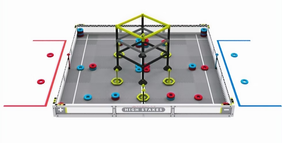
We realized that the ladder is very similar to the 2013 FRC game. Because of this, we started looking into robots from that game and came across an interesting but very efficient solution
This robot utilizes an elevator lift with claws that can pull up on the bars and then transfer to another set of claws mounted to the base of the robot. This way, they can lift back up to grab onto the next rung of the ladder.
There are a few very important things to note about this design however:
- FRC has less limitations for materials and mechanical parts meaning we would have to replace a belt powered lift and create custom linear slides
- There motors are way more powerful than ours, meaning we will need to be attentive to mechanical advantage
- The tower is angled in, while our tower is straight
Considering these things, we are able to begin finalizing a design.
Design Criteria
I settled on the following things I want out of our hang mechanism:
- Power Transmission Off (PTO) from the drive system to add 6 motors of power to the hang
- Winch system with small diameter for a strong speed to torque ratio
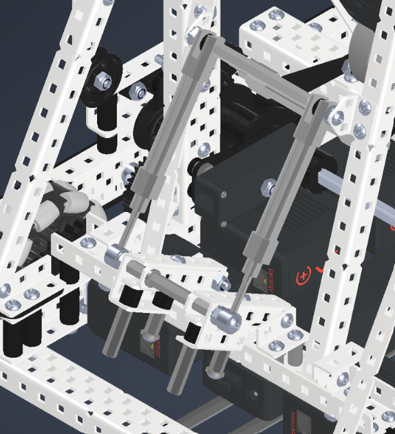
- Hinged, hard mounted hooks to make transferring between stages smoother
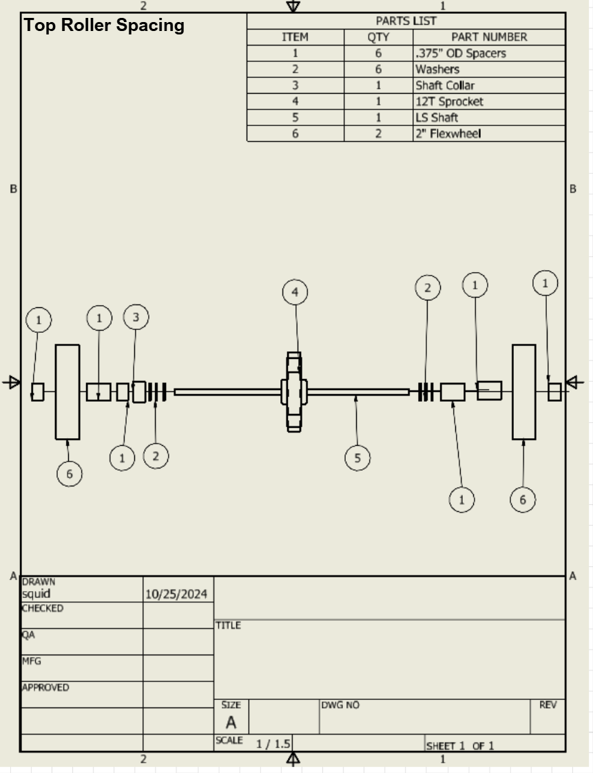
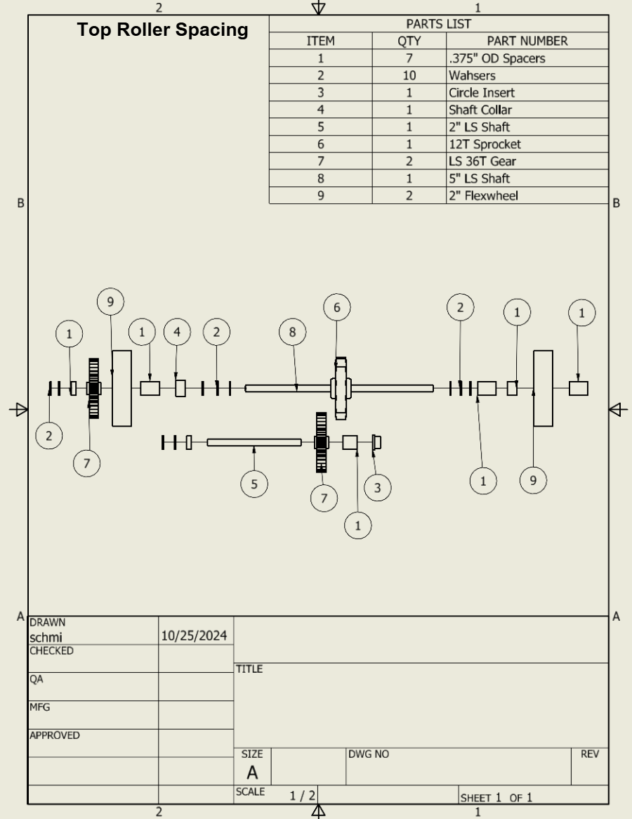
- Custom linear slides using laser cut plastic and custom rollers
- Continuous string lifting system to replace belt
I am now able to begin designing with these criteria in mind:
Version 1


At this stage in the design, I had figured out the chassis and towers/slides, but as I was sketching out the positions of the other parts of the robot, I realized there may be a spacing problem.
| Criteria |
Meets Criteria |
Does Not Meet Criteria |
Notes/Changes |
| Fast Drive |
X | ||
| Includes space for all subsystems |
X | Intakes and electronics mounting didn’t have enough space. | |
| PTO positioned under lift for easy string routing |
Robot failed at subsystem space, so the CAD was not completed. | ||
| Center of Gravity |
Robot failed at subsystem space, so the CAD was not completed. |
Version 2
For this version of the design, I changed up the tower mounting to try and make more space. I also modified the lift to be a 3 stage elevator so that it had enough reach to get to the next stage.
Early on in this design, I wanted to figure out PTO, battery, and brain placement so that we could maintain good COG while also ensuring there was enough space.
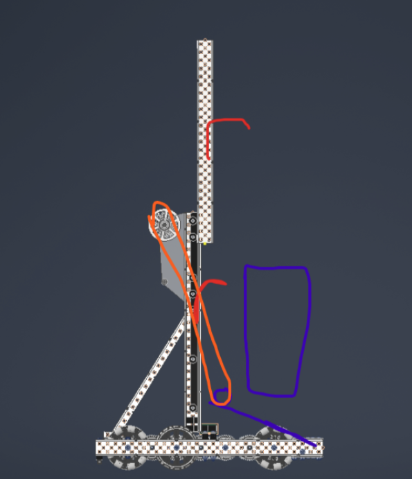
Due to the placement of the brain and the battery, I had to shift the PTO forward:
As seen by the sketch, this causes the string to need to be rerouted around a pulley and cut an almost 90 degree corner, which is really bad for mechanical advantage.
| Criteria |
Meets Criteria |
Does Not Meet Criteria |
Notes/Changes |
| Fast Drive |
X | ||
| Includes space for all subsystems |
X | ||
| PTO positioned under lift for easy string routing |
X | PTO required complicated string rerouting with poor mechanical advantage | |
| Center of Gravity |
Robot failed at PTO position so CAD was not completed |
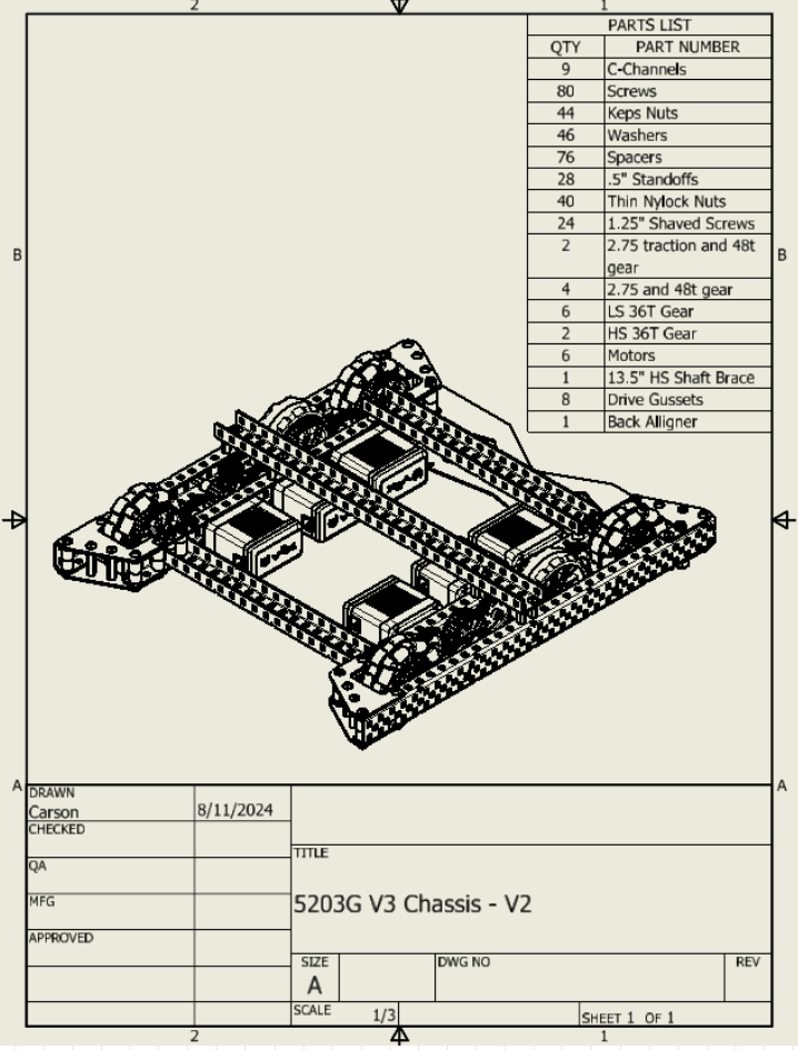
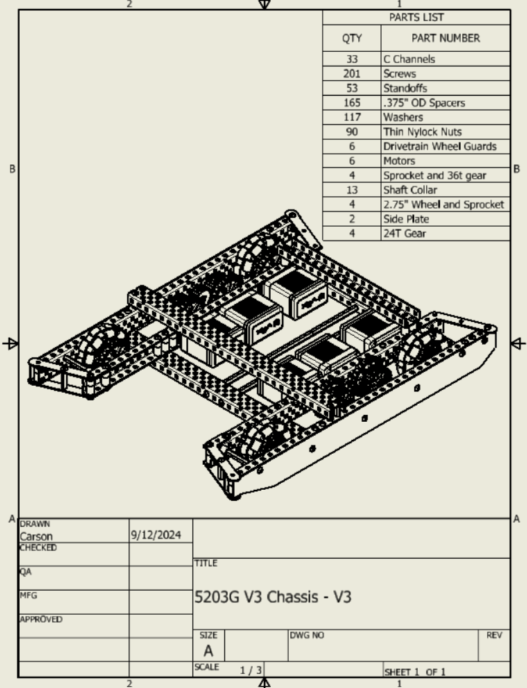
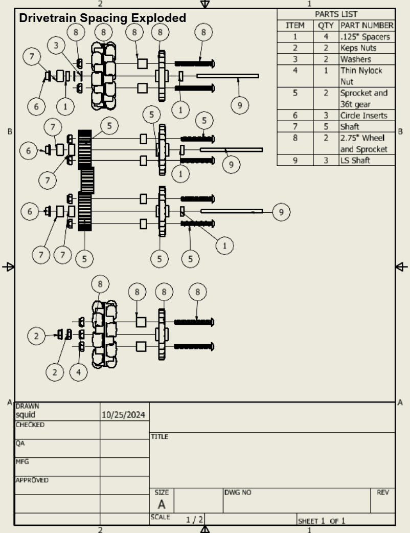
Version 3
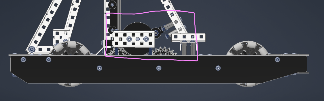
The biggest issue in the previous two versions was spacing, because of this, I am designing around a longer drivetrain by utilizing a chain drive. This allows the gears for the PTO to be put wherever they need to as well as opening up more room for subassemblies.
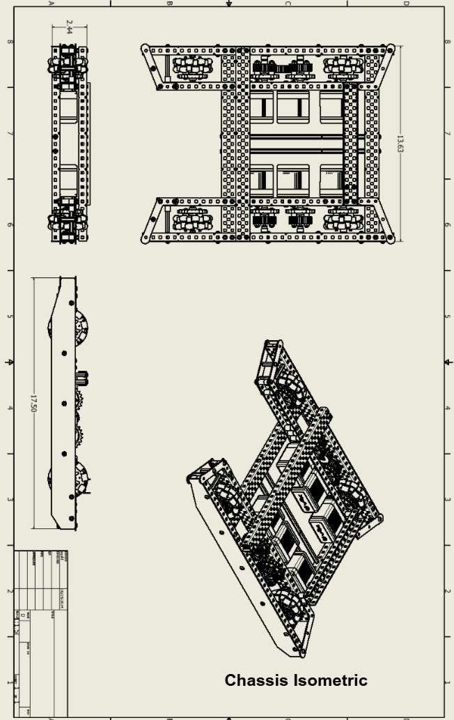
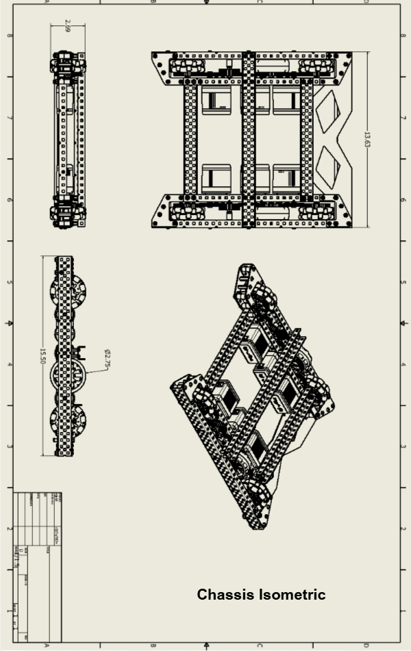
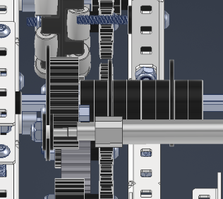
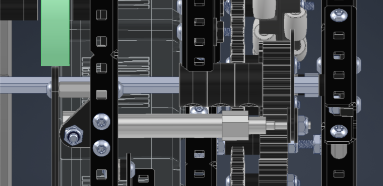
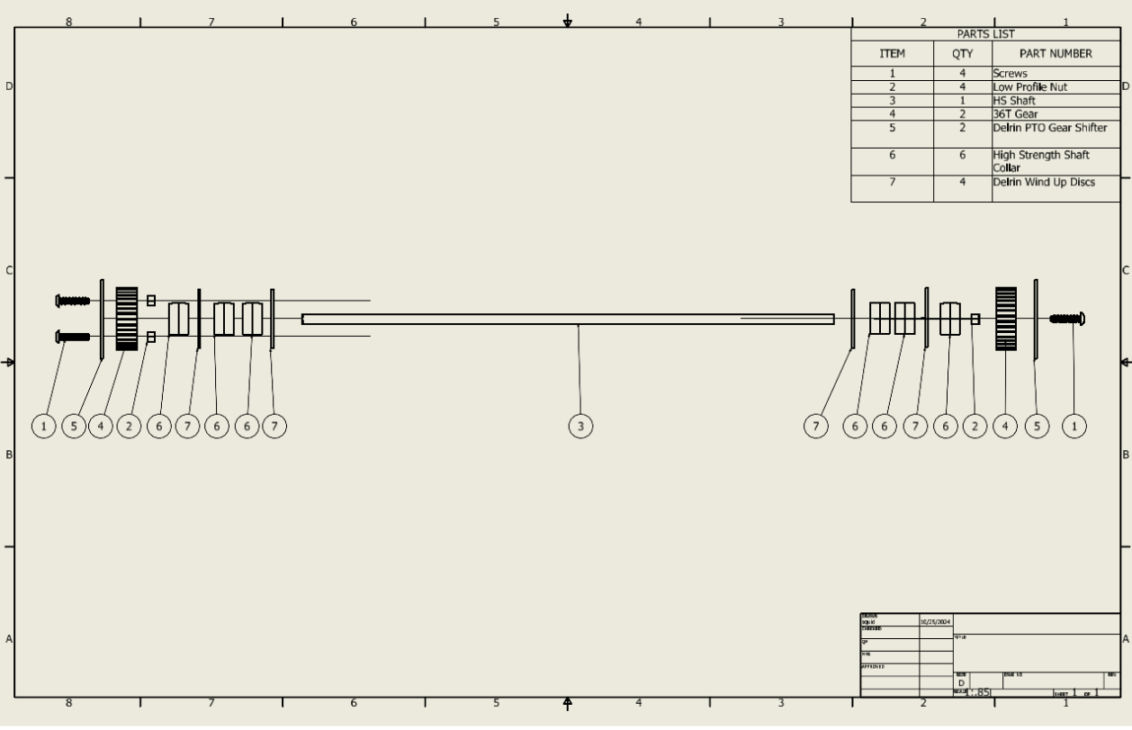
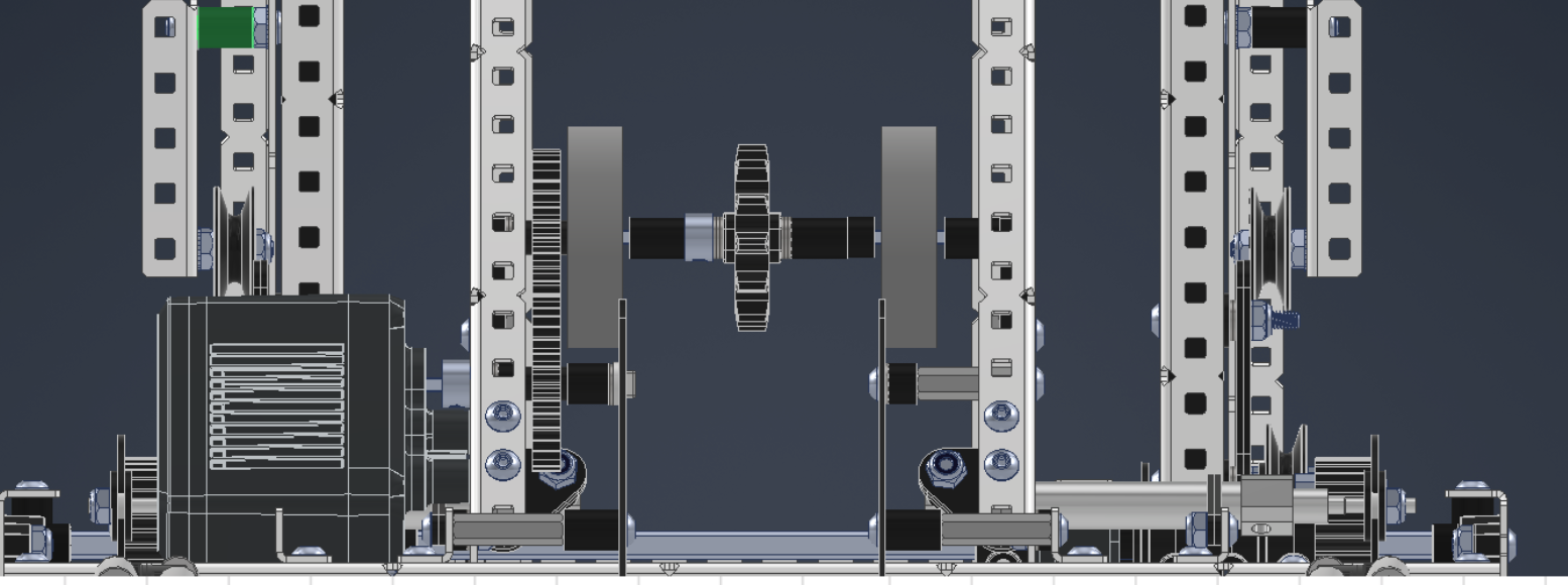
After the initial structure, I was pretty confident in the new improvements spacing wise. Next I focused on designing the PTO.
Next I worked on the intake design.
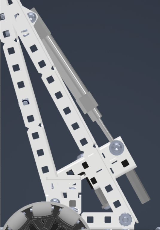
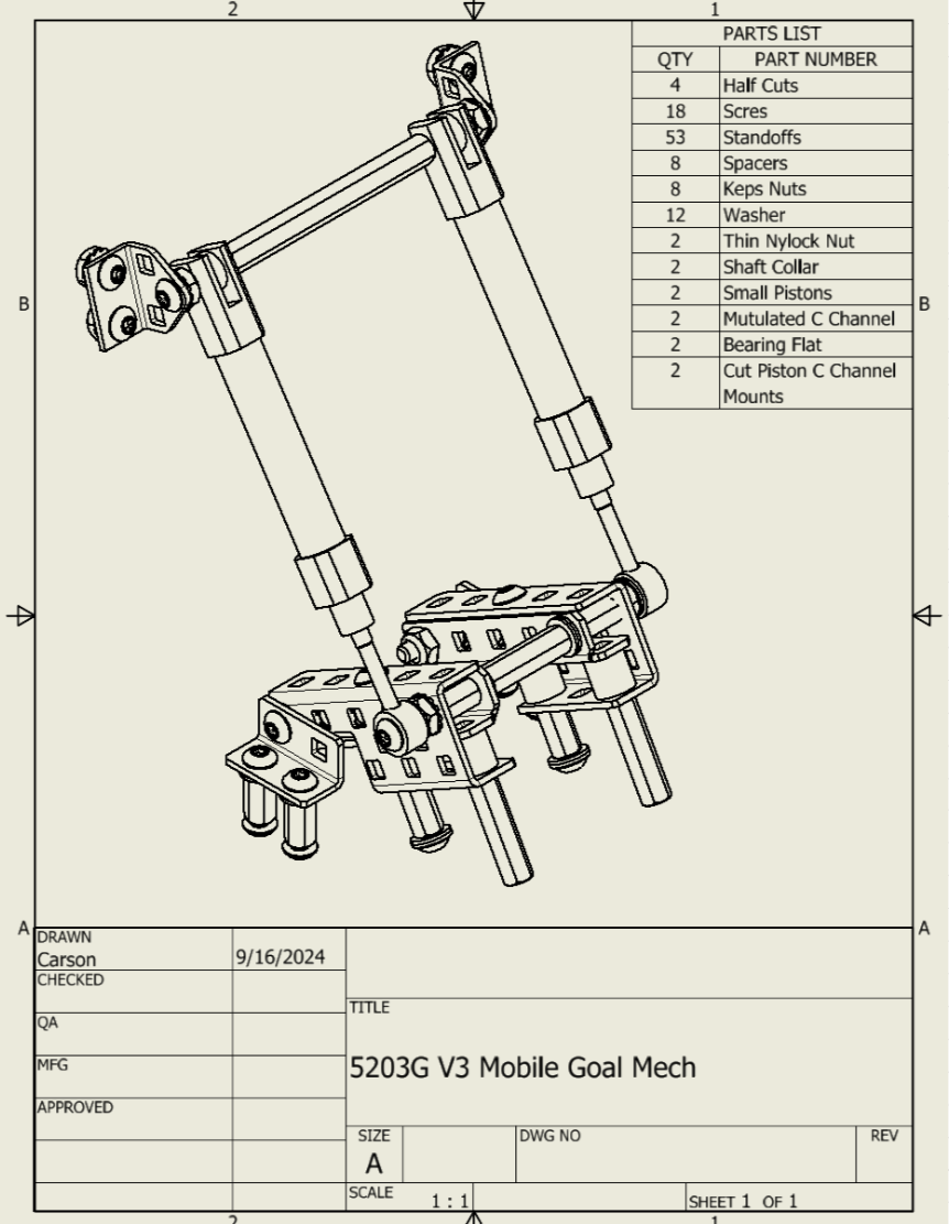
Now that the intake design is done, everything seems to be coming together, the next step was the mobile goal clamp.

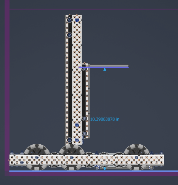
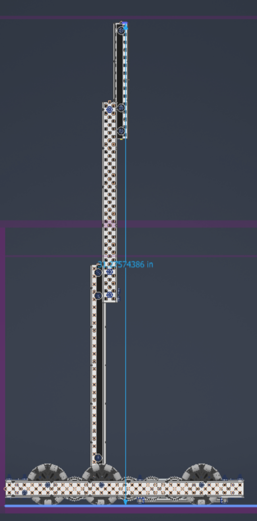
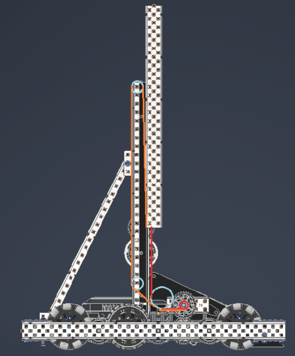
Finally, I added a very similar 3 stage elevator as what I had already designed for version 2.
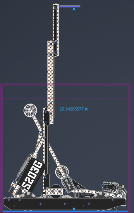
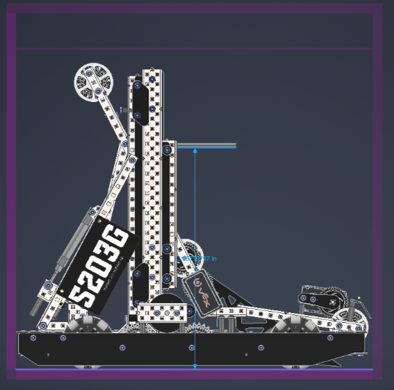
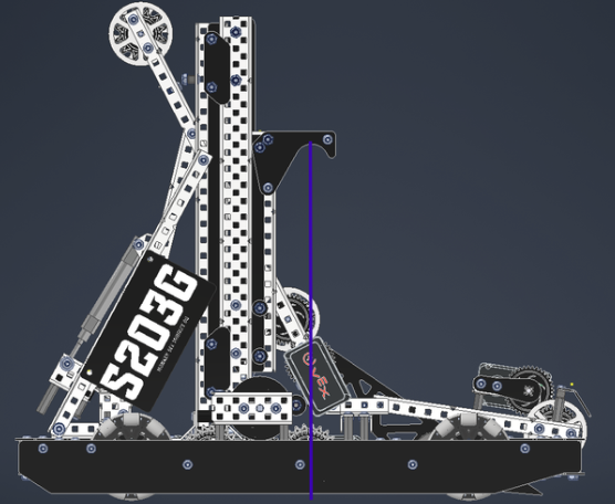
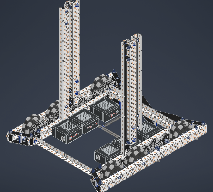
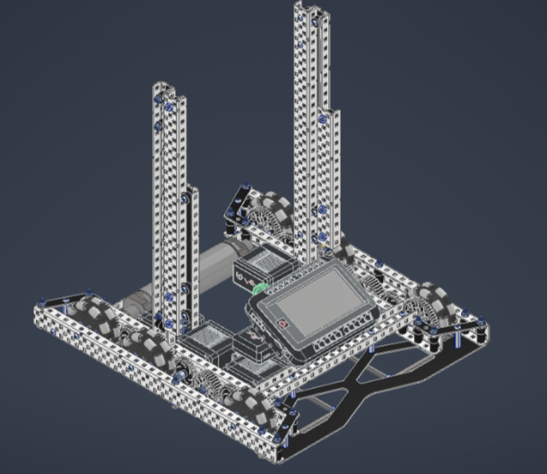
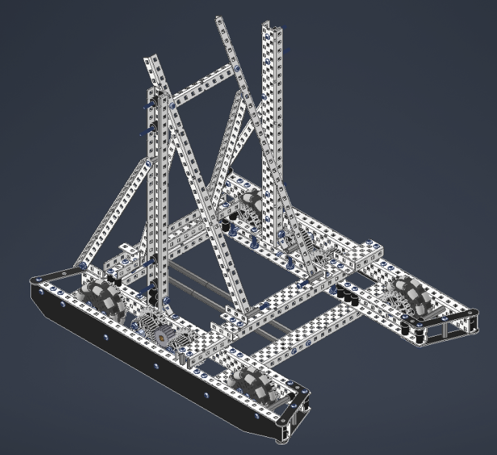
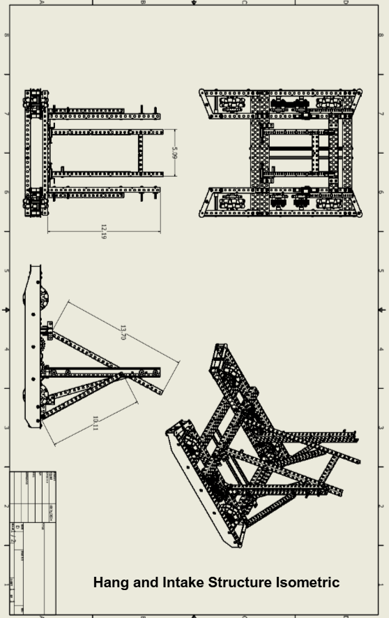
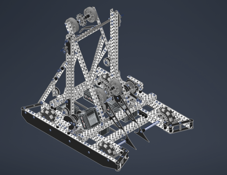
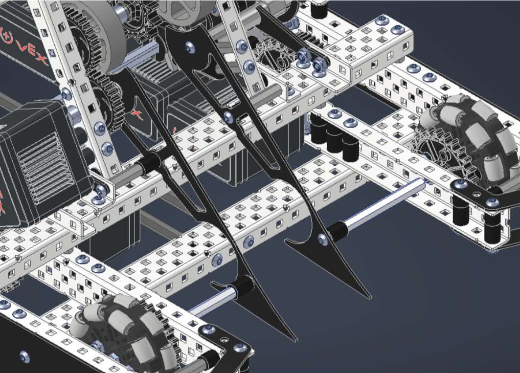
Final Design:
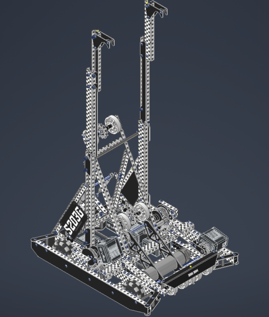
Assembly
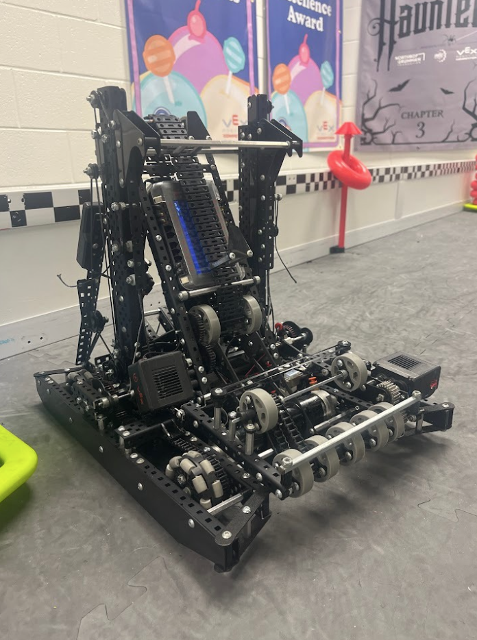
We spent lots of time building, testing, and tweaking this design to get it to work. More information on that process can be found in our design notebook:
https://heyzine.com/flip-book/7005792d0e.html#page/400
Code
As the lead programmer on the team, I also had to create and code a macro for the hang. I utilized a rotational sensor to keep track of the position of the winch. I also utilized a gyro sensor to make sure the robot was level at each tier.
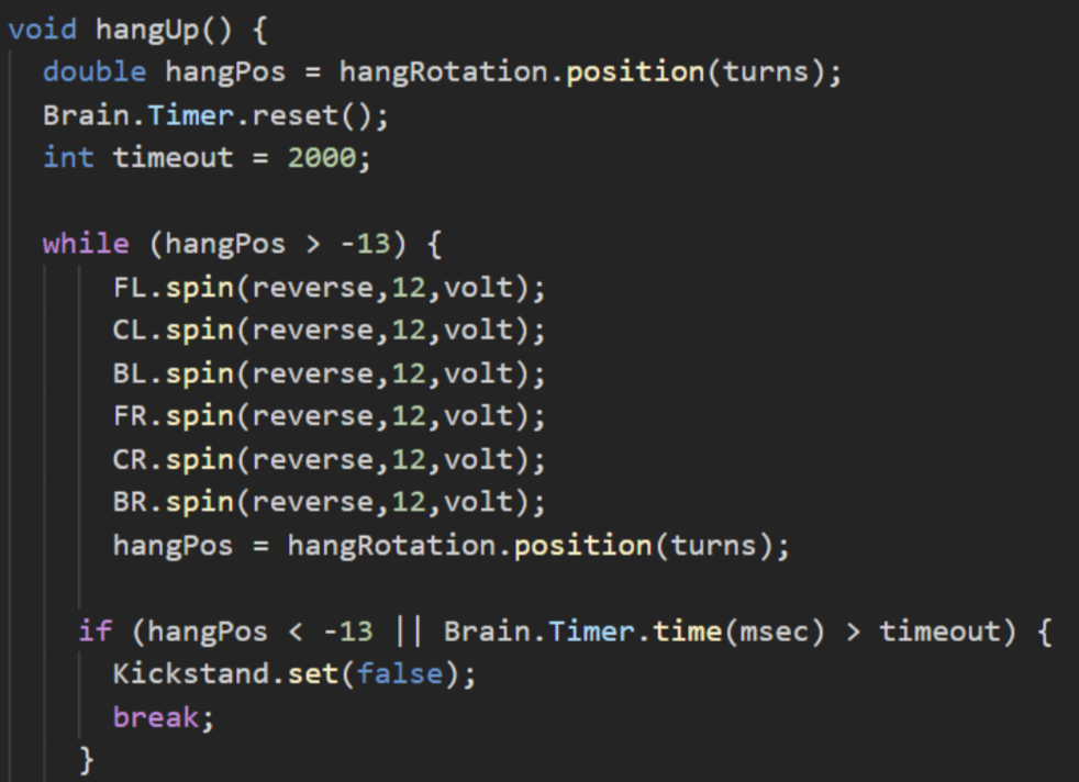
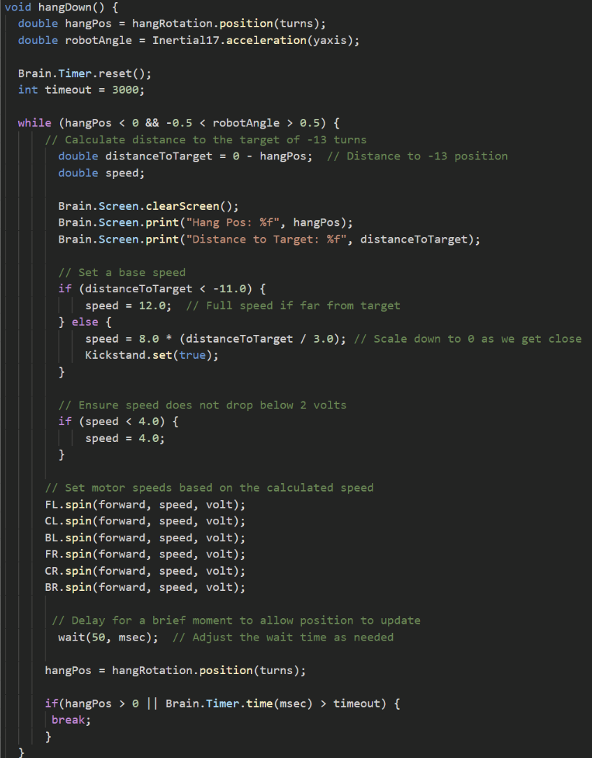
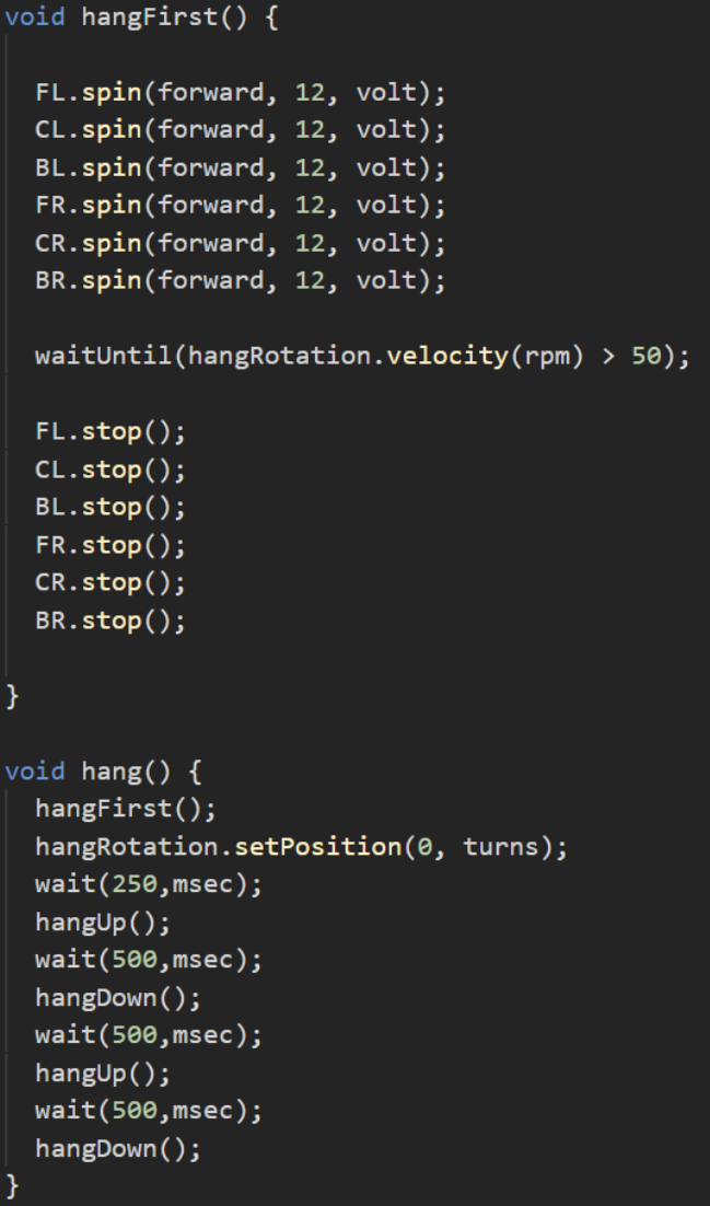
This macro allowed us to hang consistently and reliably.
Performance
Final Thoughts:
This project was super rewarding to work on. It was so cool to share this complex mechanical design with other teams from around the country and even the world. I competed in VEX Robotics for all 4 years of high school, for other examples of my work on the team, check out our YouTube page: