


Problem Statement
The current end of arm tooling allows the part to flex and slide causing the plastic clips to miss insertion. A new end of arm tool is needed to solve this problem and have a stronger hold.
Brainstorming and Initial Design
I first started with ideation and initial sketching, so I could flush initial ideas out on to paper. At first, the goal was to create a fixture that would help square up the part before being grabbed by the robot.
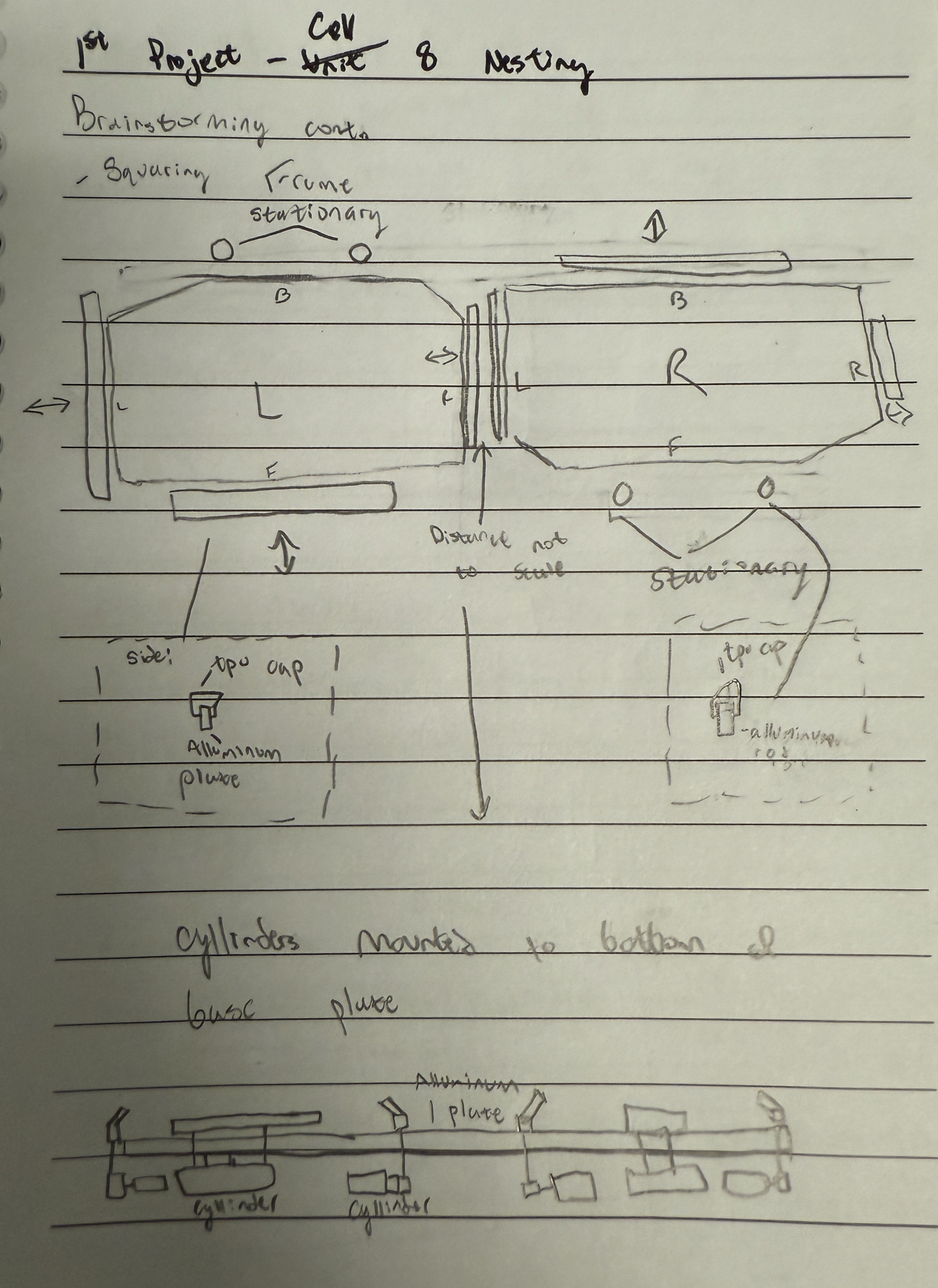
After going to the plant floor and continuing to evaluate the problem at hand, I quickly realized that the corners of the part, where clips were being inserted, could flex and slide which had to do with the tool holding the part itself.
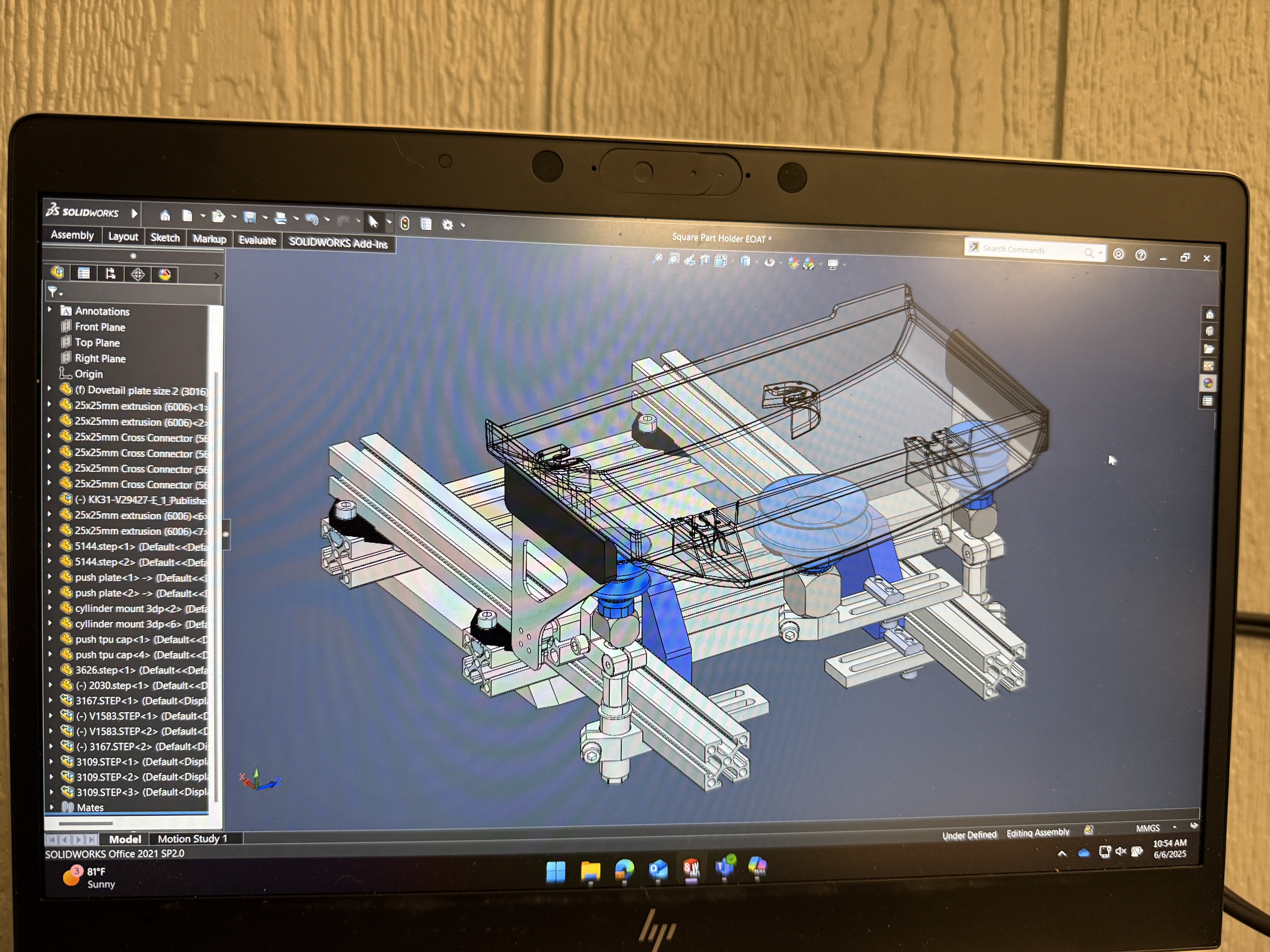
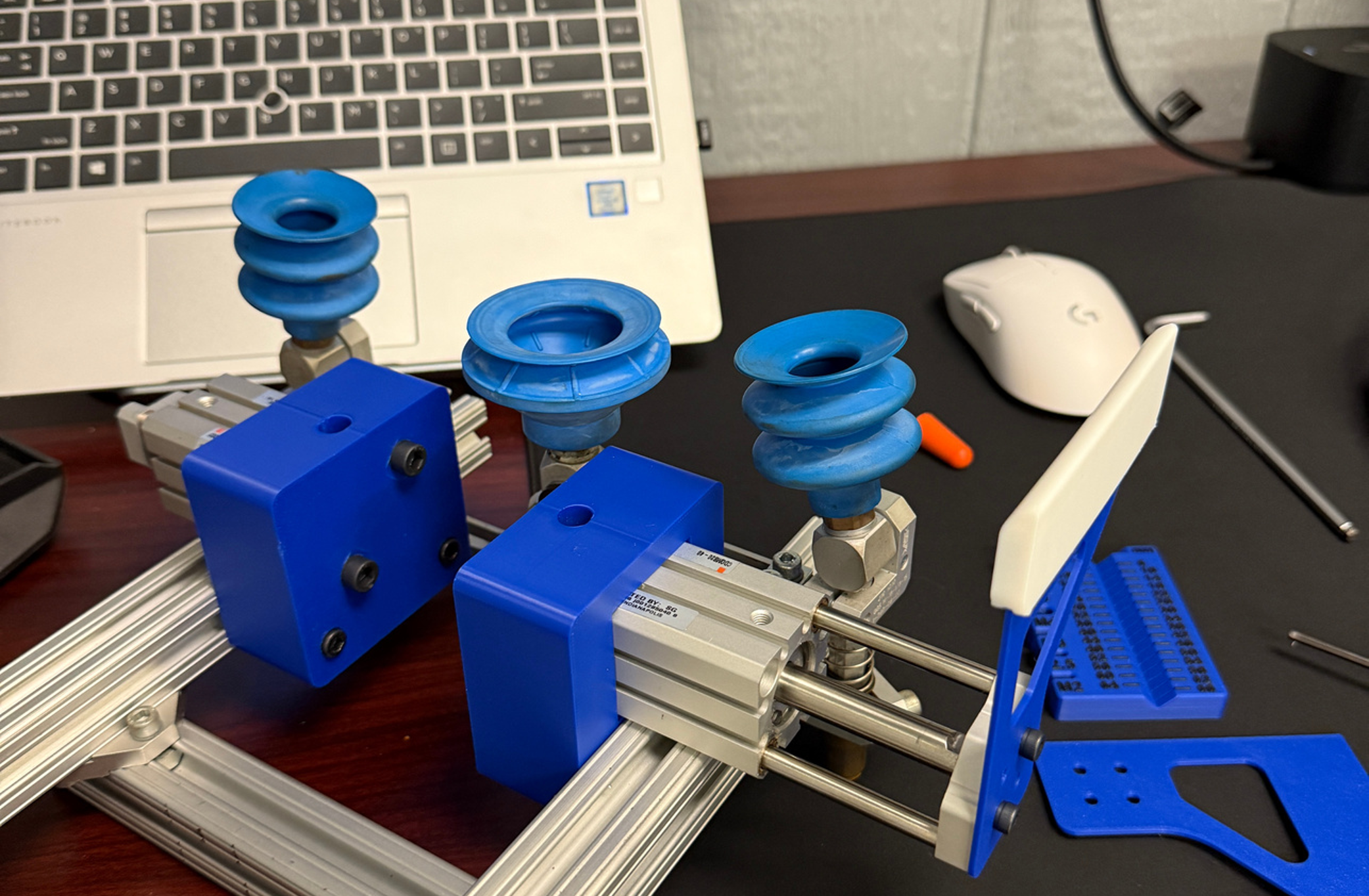
This led to my initial design. I started with CAD in SolidWorks, while also assembling prototypes to see how the part would interact with the vacuum cups.
Version 1
Version 1 Prototyping
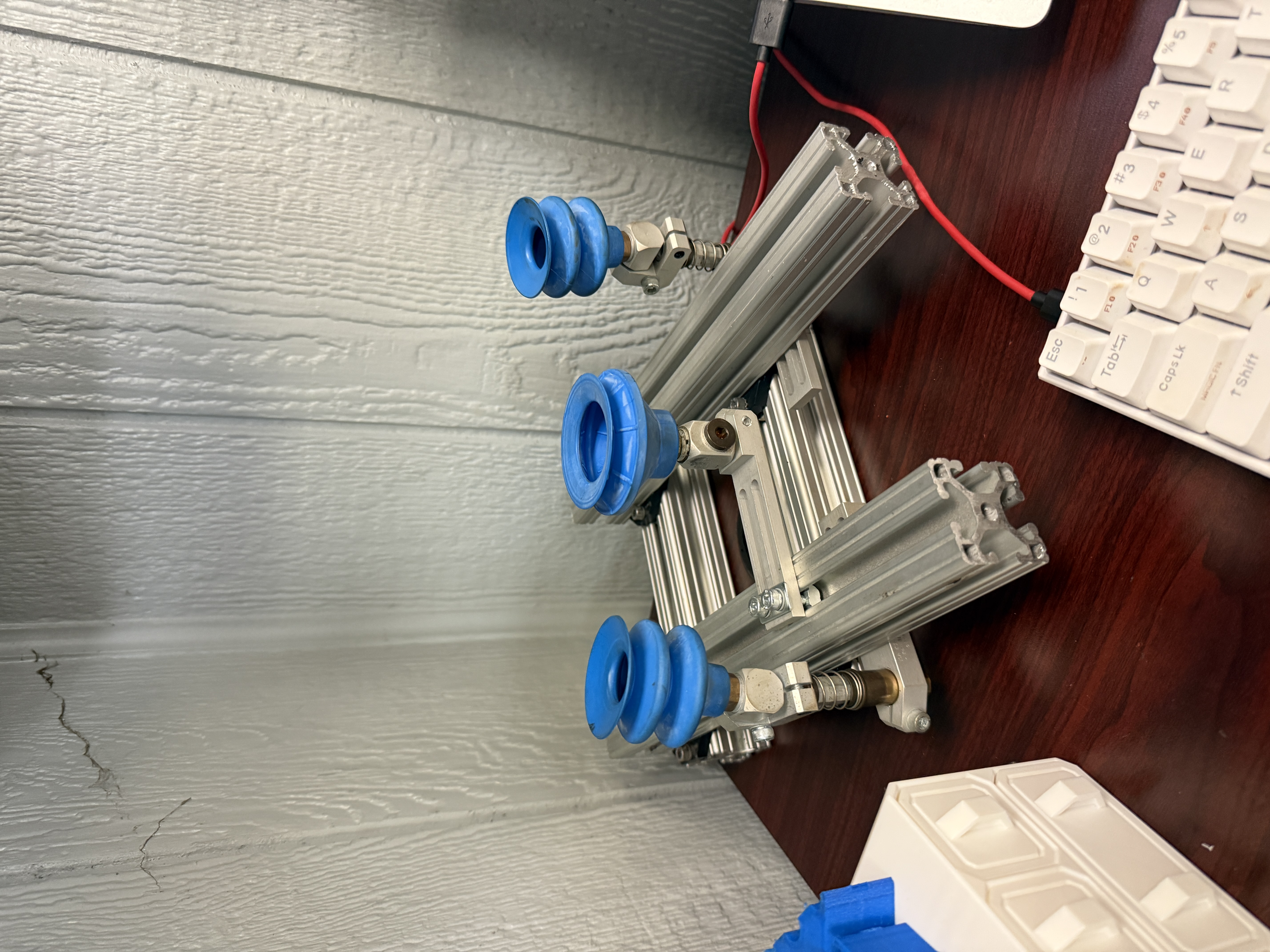
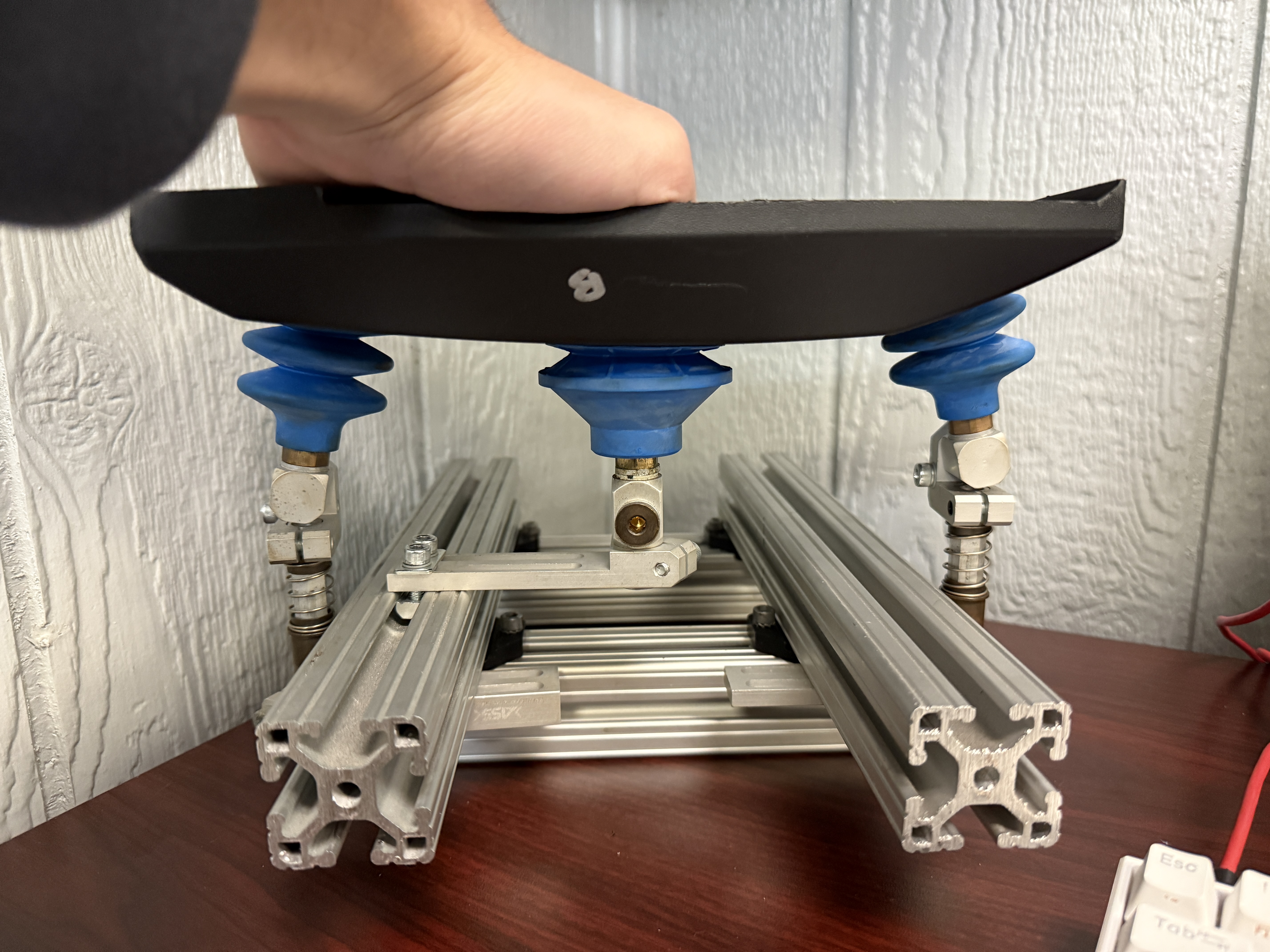
Next, I began printing parts to do some rapid prototyping to ensure my future machined parts work the way I want them to. Through this process, I was already making little improvements to ensure everything would work consistently and reliably.
I also began hooking up the air tubes throughout this process so I could use the air compressor in the automation lab to do some version 1 testing. The video below shows that testing.
Version 2
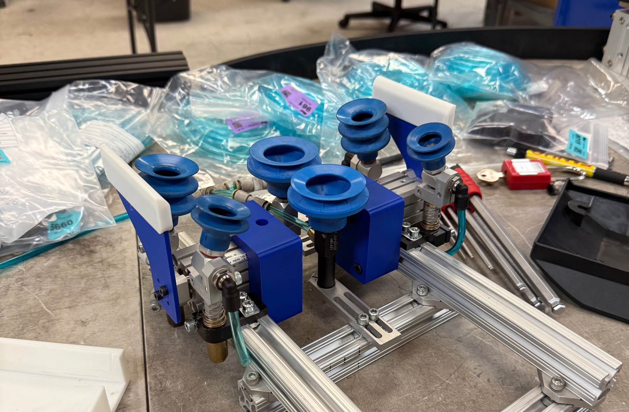
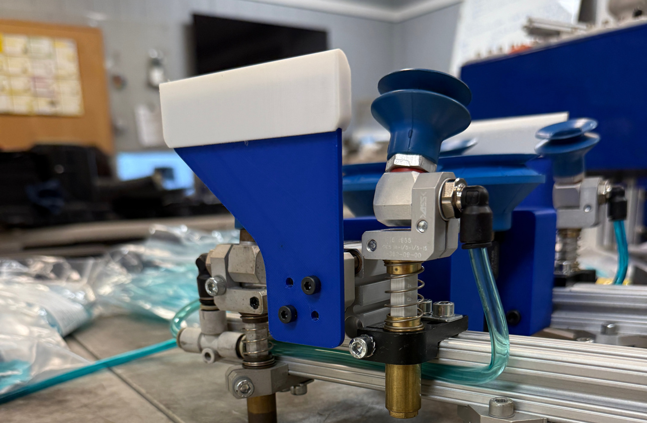
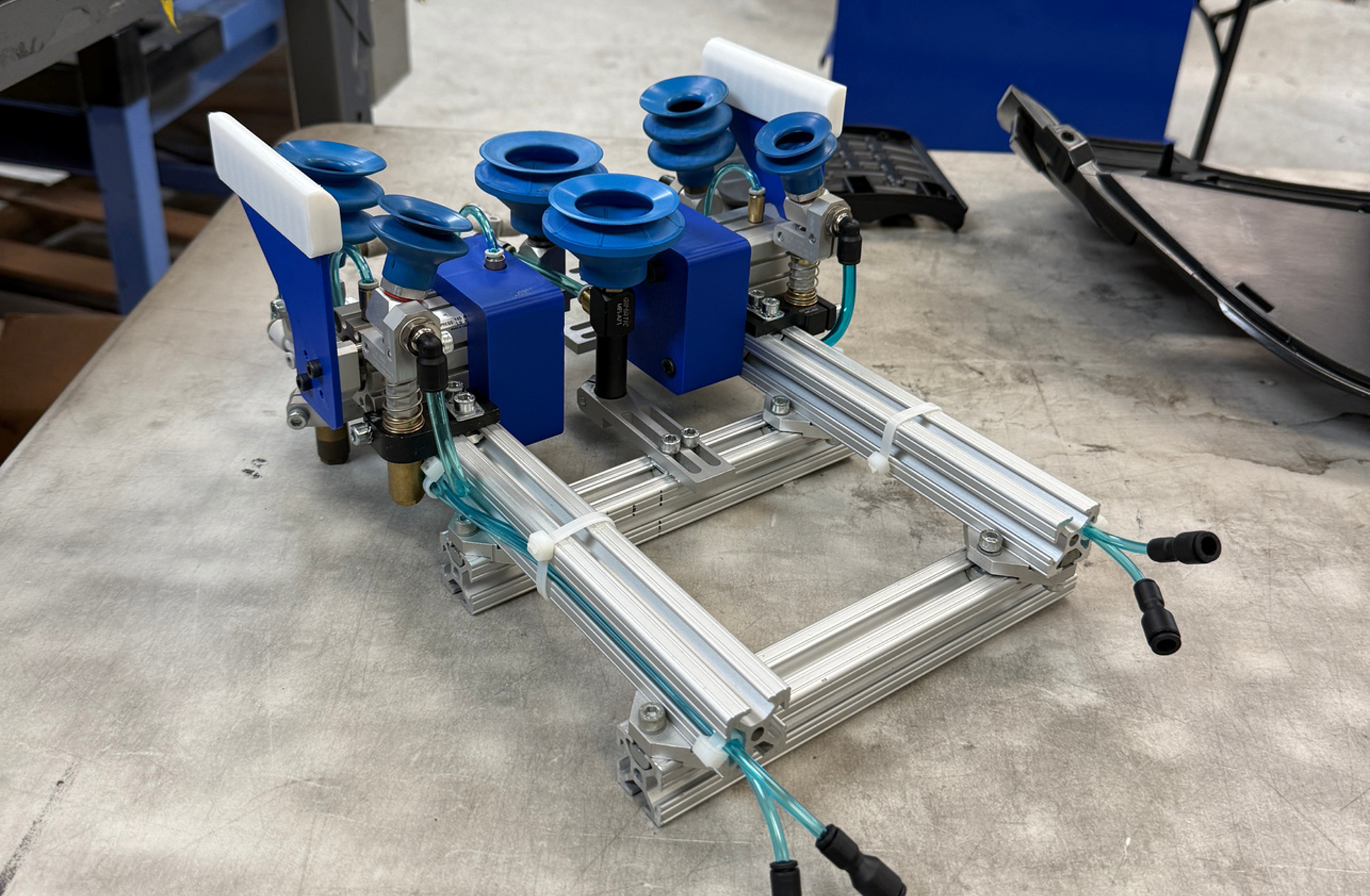
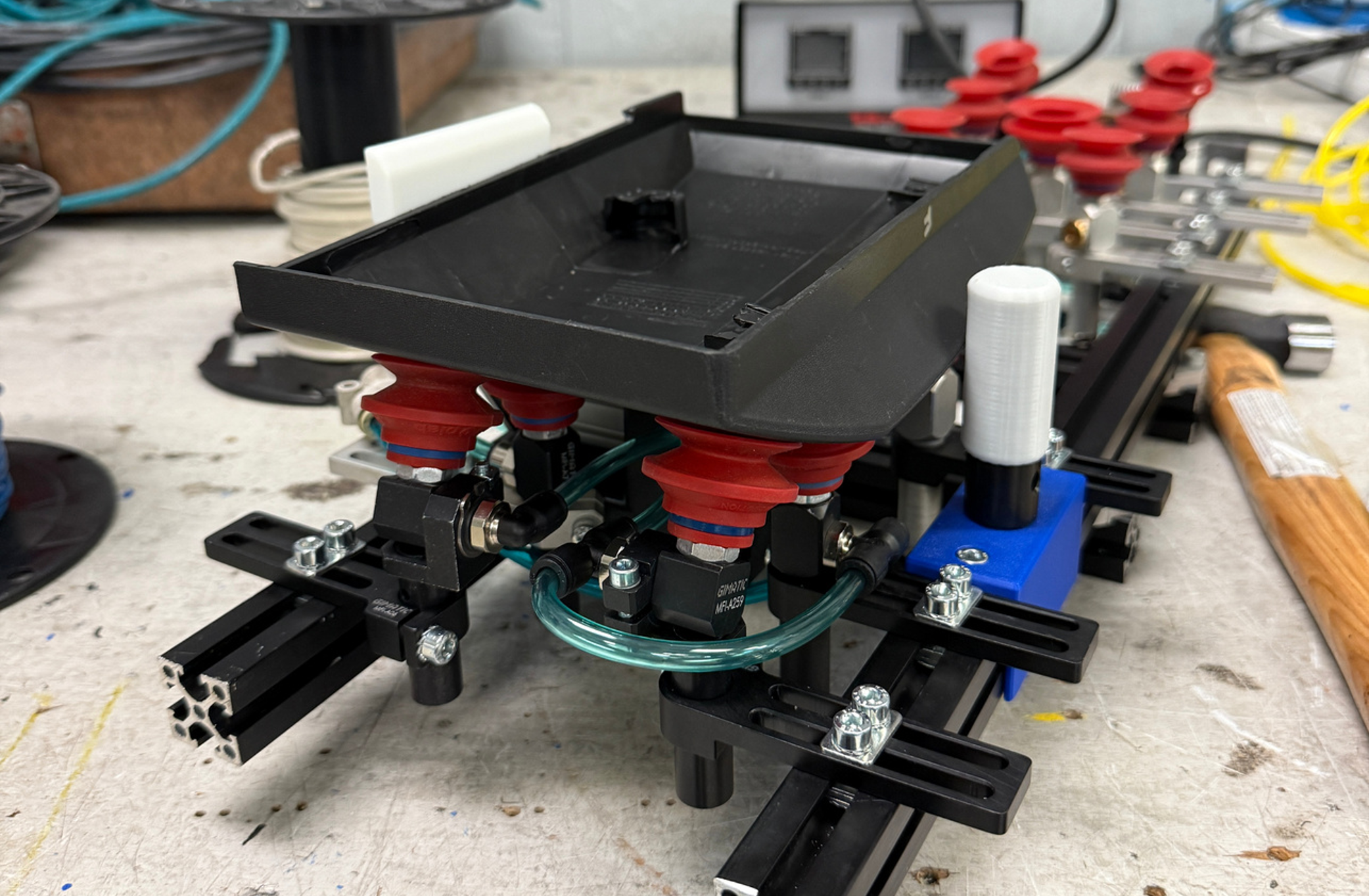
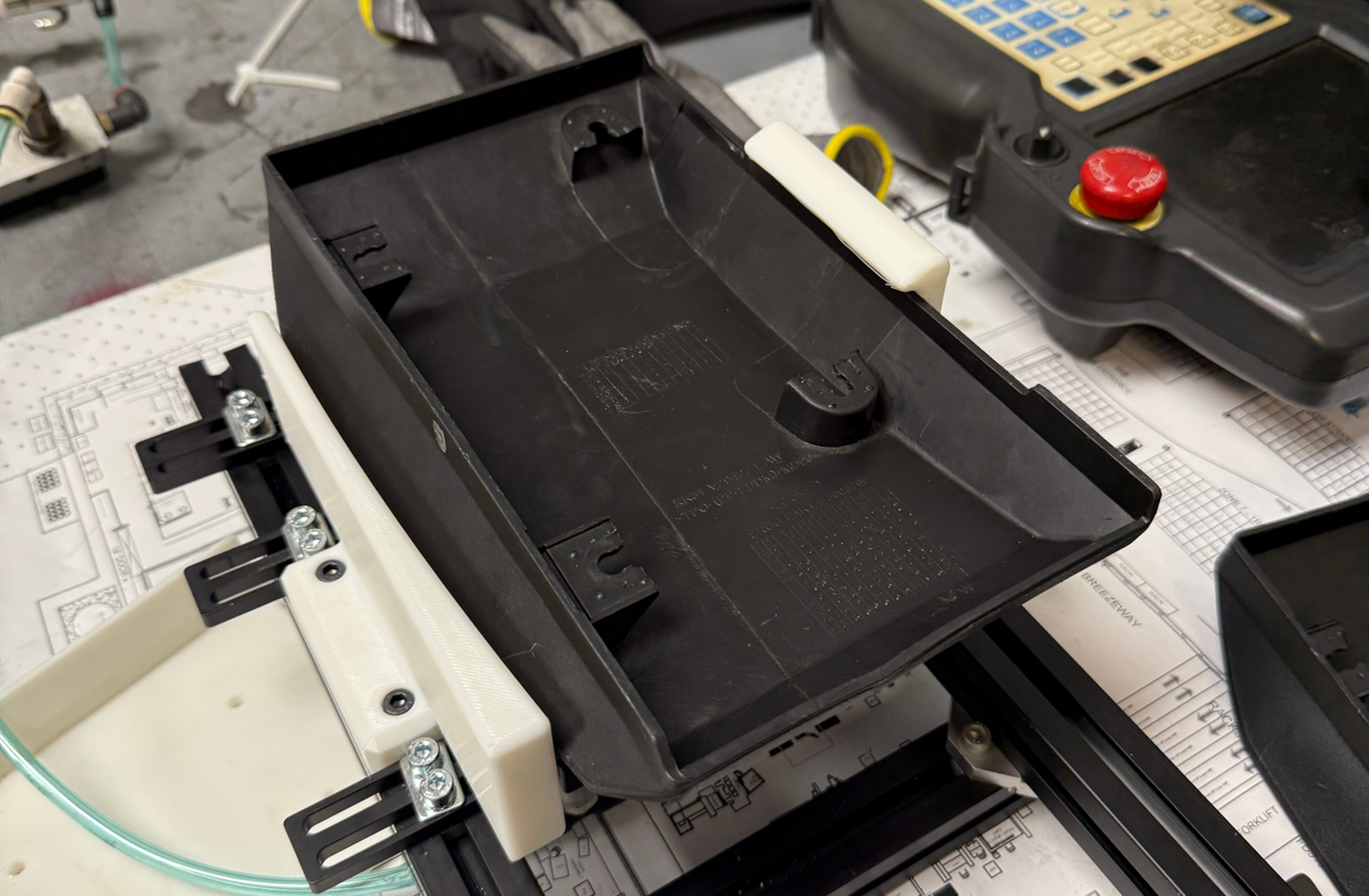
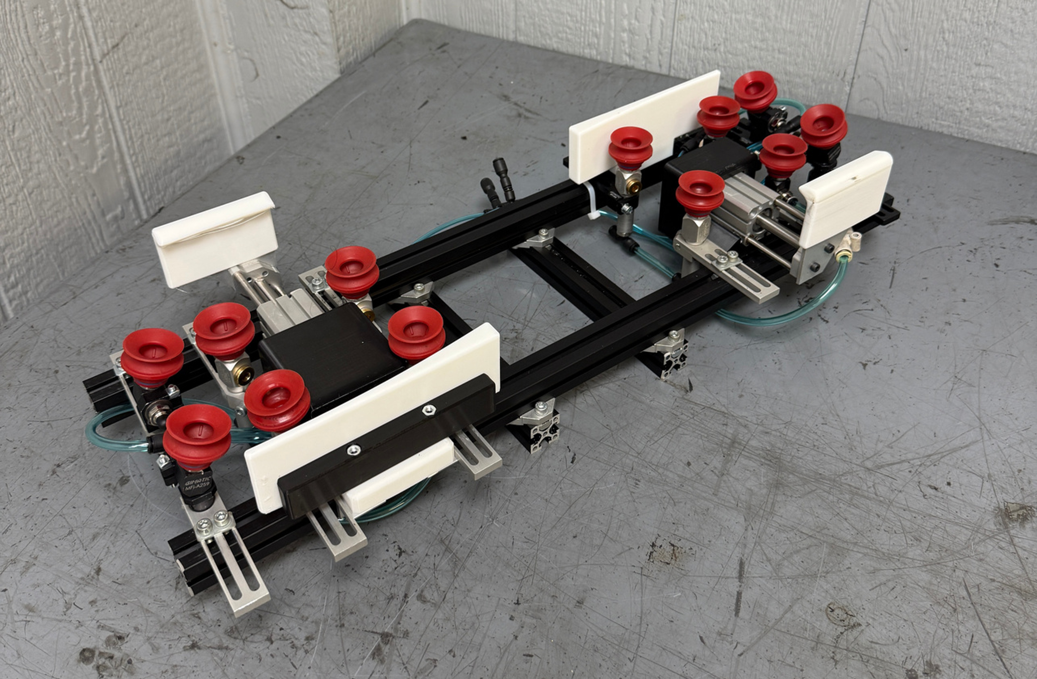
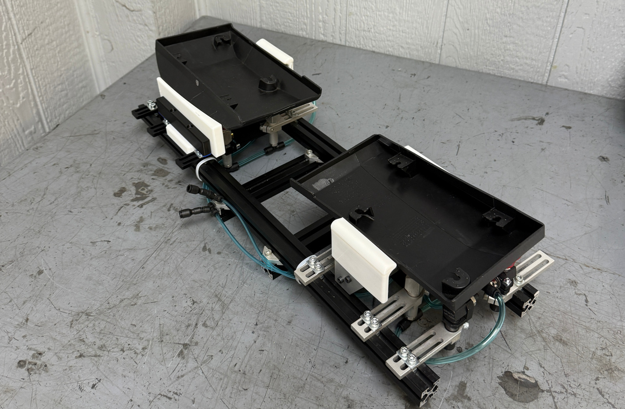
After getting some feedback from my boss, the senior automation engineer, I moved towards using a one-sided clamp system that had a hard mounted arm on the other side. The robot is accurate enough to line up one side and be clamped on the other and overall reduces complexity. I also wanted to make it pick up both parts at once instead of one at a time. They are placed initially in a side-by-side configuration, so I measured what that was and doubled what I had on the other side.
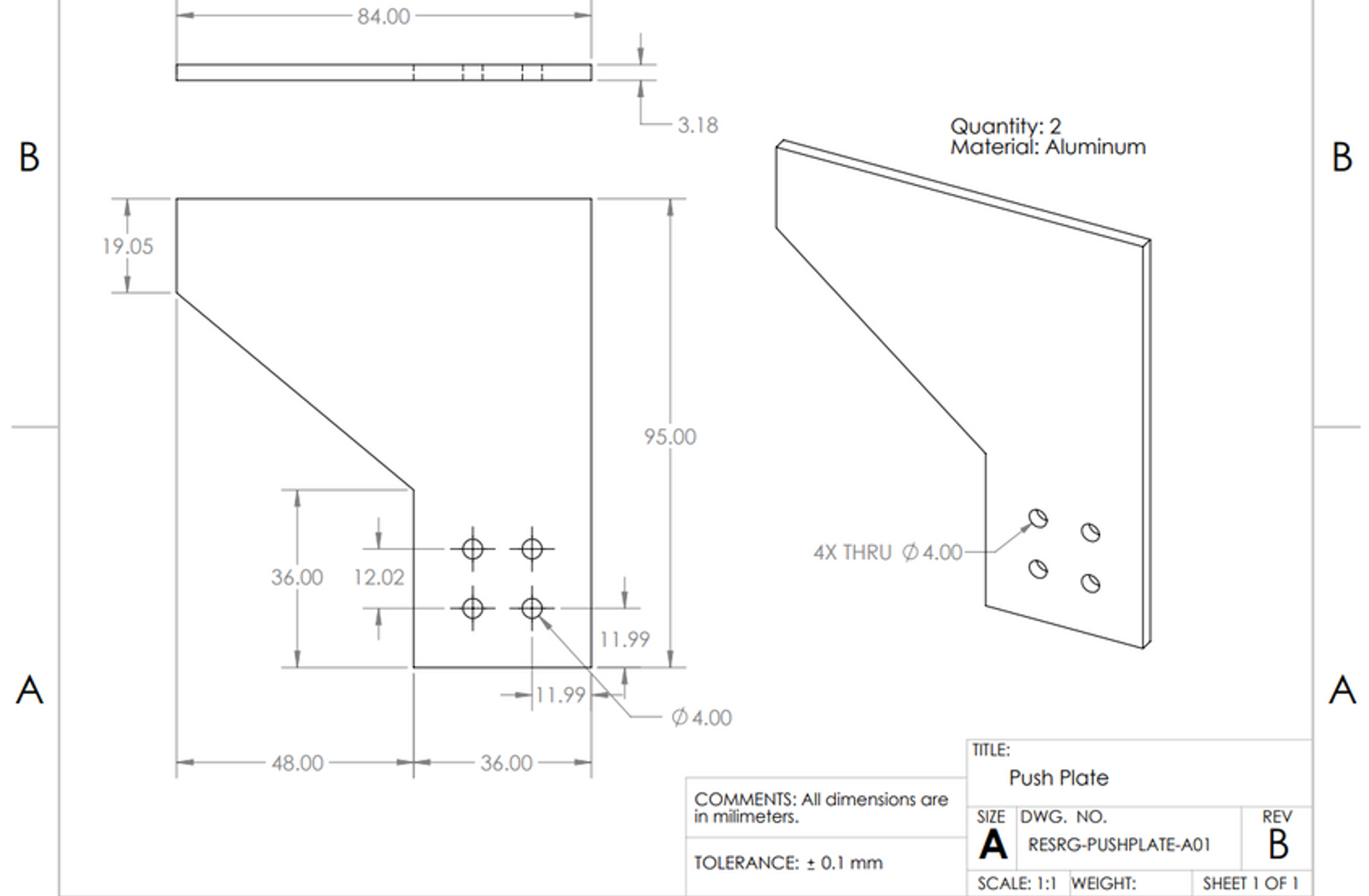
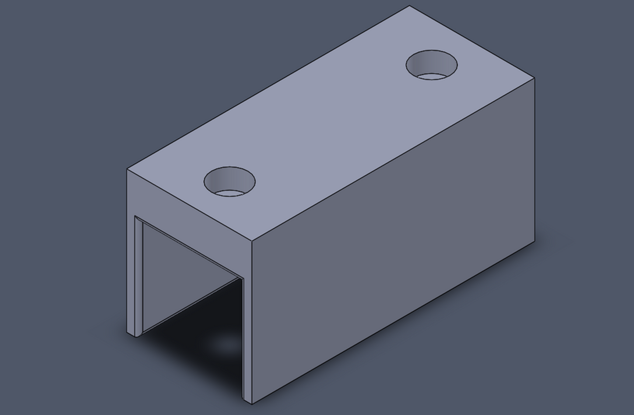
Because my printed clamp parts work, I was able to get them made out of aluminum. While creating the drawing file, I realized there was already a part from EMI very similar to what I was designing. To save on cost and time, I used the bandsaw and drill press to turn the EMI part into one that would work for my clamp. I also used TPU finger parts slid over the aluminum to ensure that class A and class B surfaces remained unmarked.
Next, I worked on creating a mount for the arms. This is another EMI part that I cut down and slid anther TPU protector part on top. I also designed a 3D printed mount for the rod to mount to the extrusion in the correct position.
Version 2.1
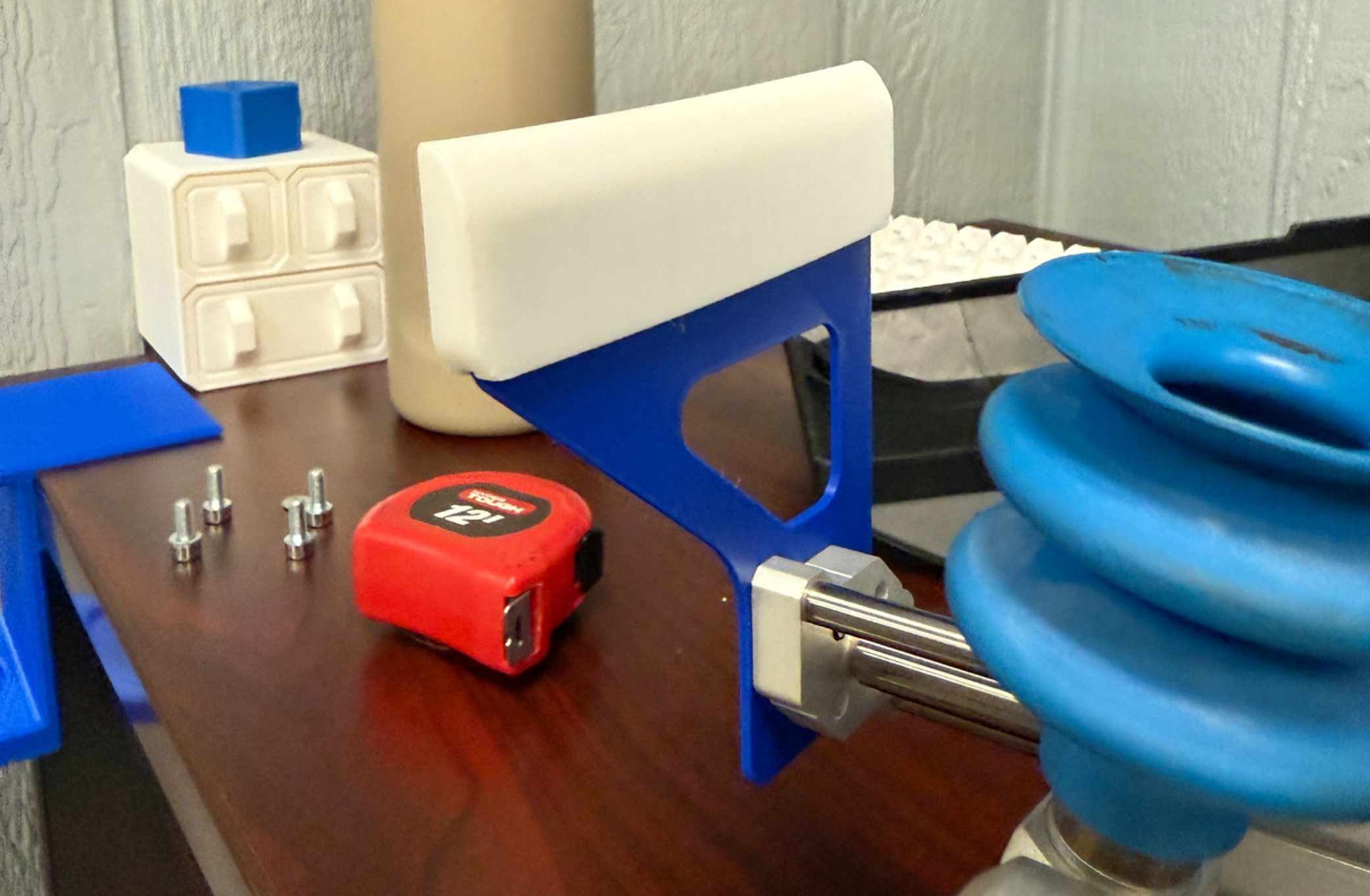
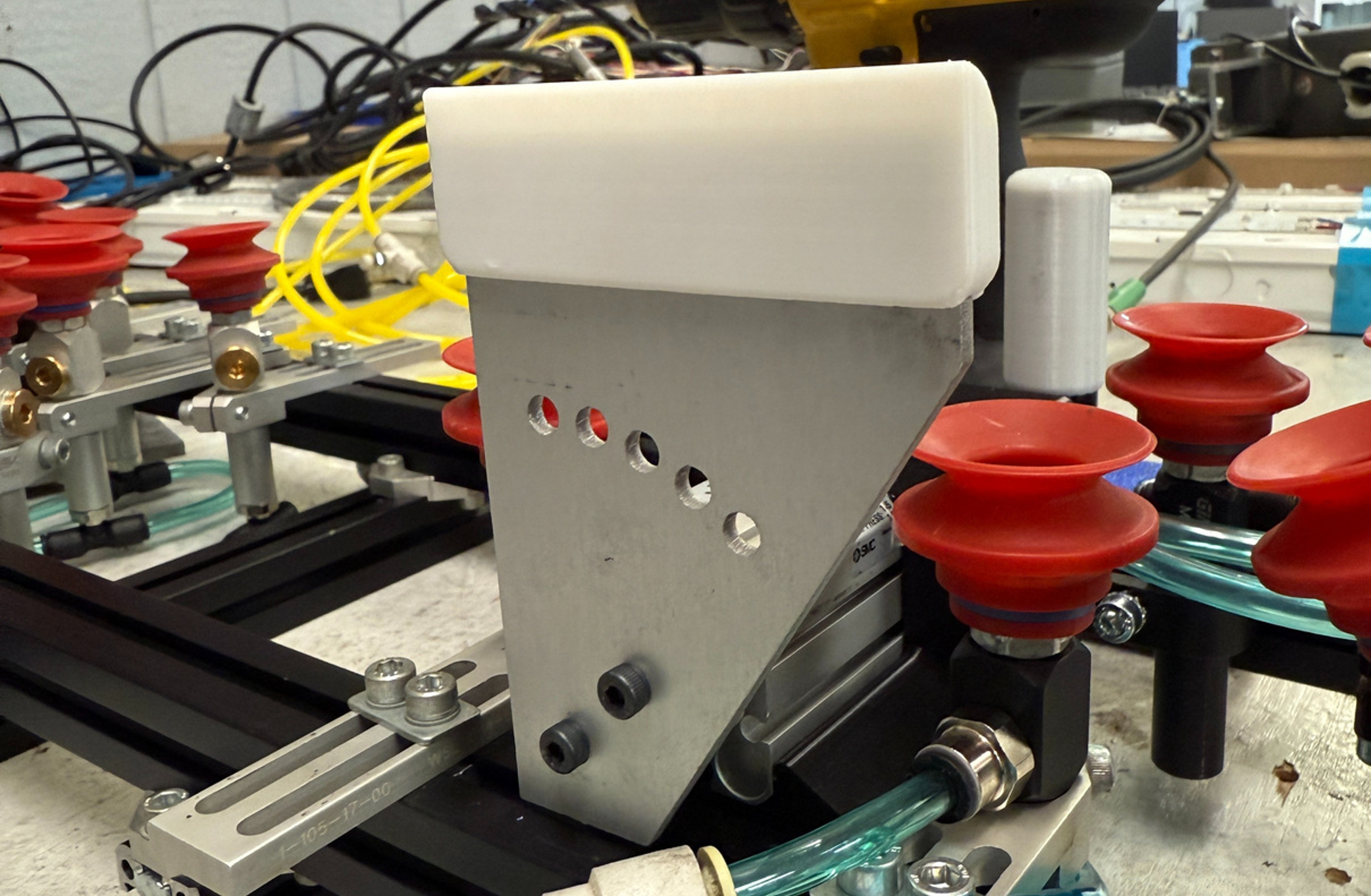
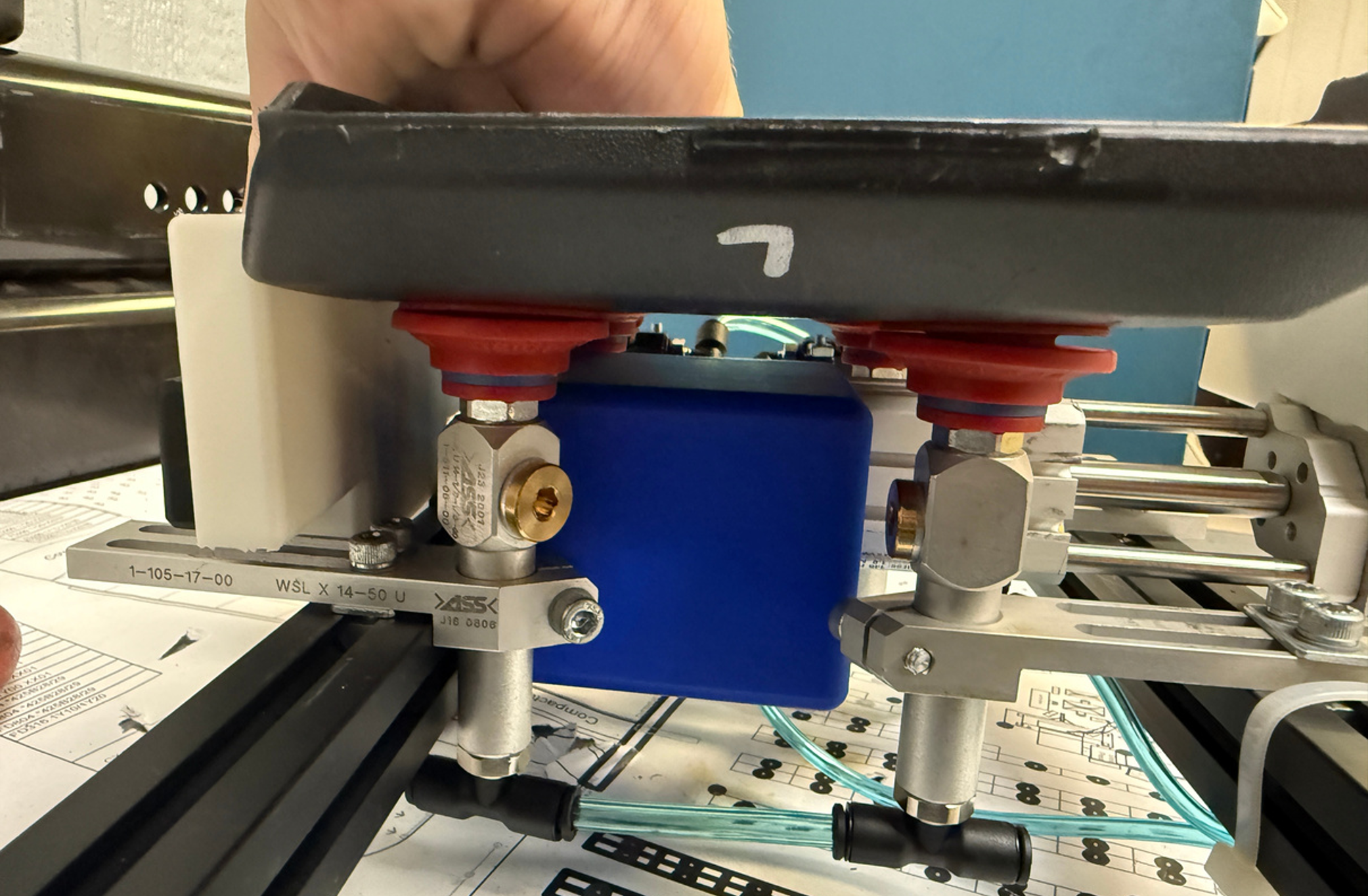
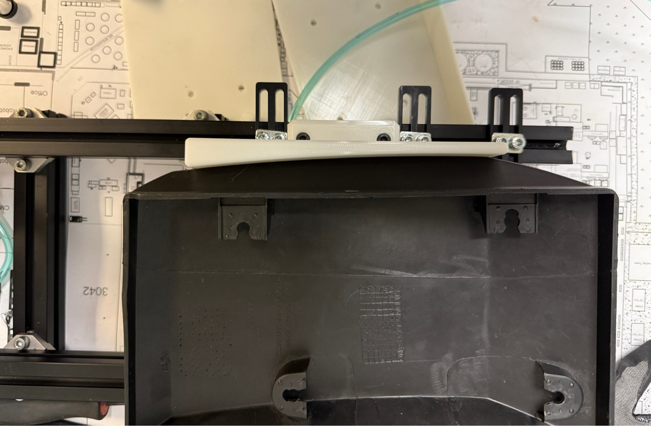
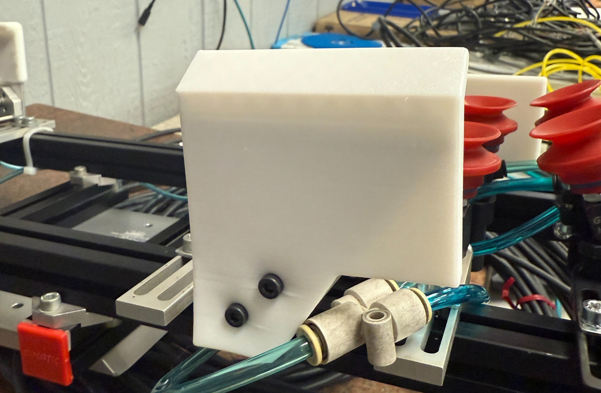
The biggest problem with this design is that the rod acts like a pivot point and the part can attempt to turn around it when clips are inserted. Also, it has the potential to dent the parts when they are really hot right after coming out of the press. To fix these issues, I designed a TPU compliant part for the clamp to push against that follows the curve of the part. This not only helps with alignment but also with grip.
Finally, I extended my TPU part on the clamp plate to allow for screw holes.
Version 2.1 Testing
Now it was time to test this new version. Some videos of different tests, including a pickup test and clip insertion test are below:
Implementation
After very successful testing, we were ready to bring it down to the floor to put into the automation cell!
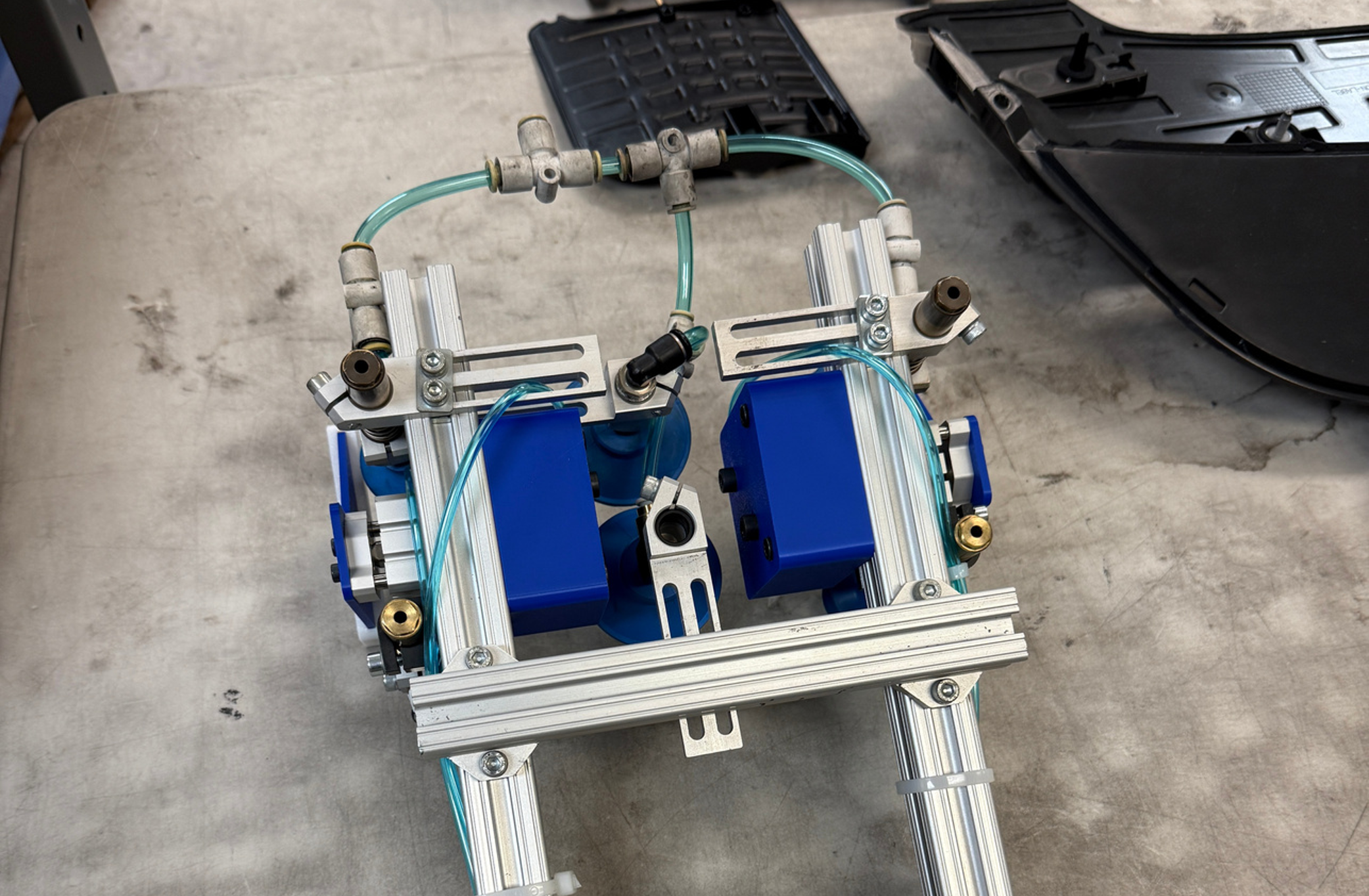
We first had to rerun tubing for the new clamps:

Then we were able to mount it and get it hooked up and programmed!
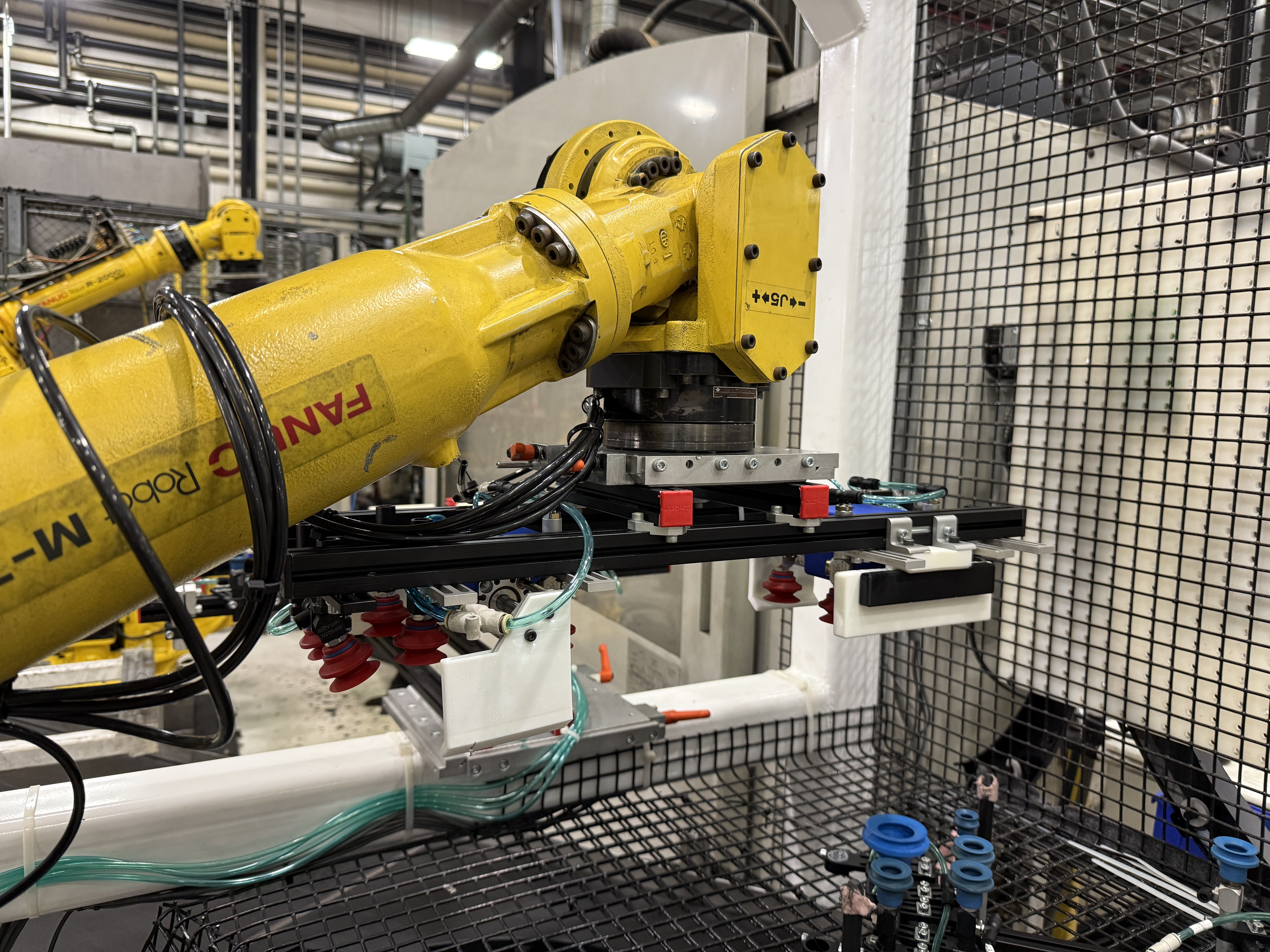
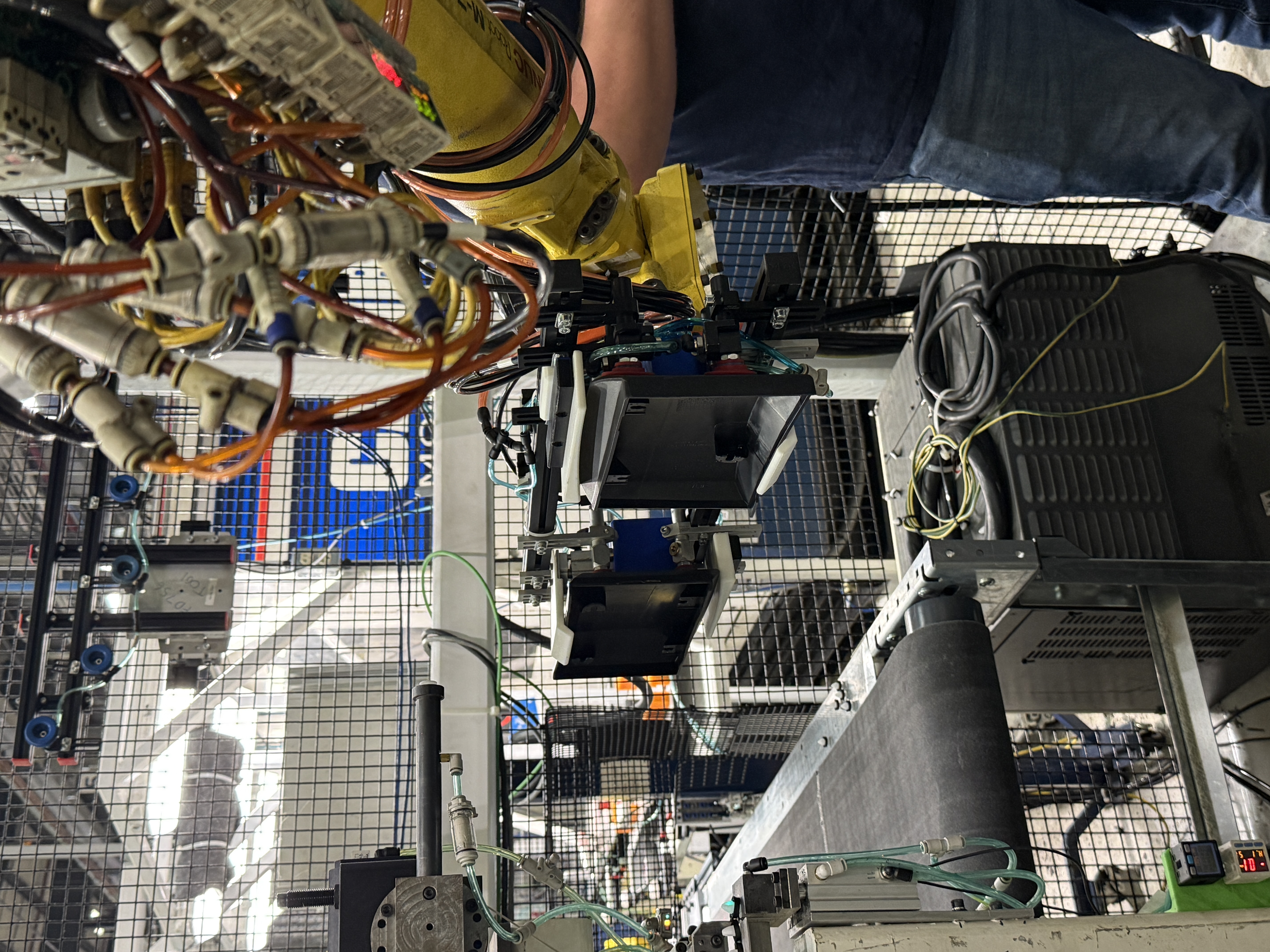
Initial Performance Testing:
Final Thoughts
This project was super fun and rewarding to work on! It was an invaluable experience to be able to independently take an automation project like this from start to finish and get to do so much hands-on work all at the same time. Thanks to RESRG Automotive for the incredible internship opportunity!