


Why We Built The Device
The problem our team is addressing is the need for a simple, low cost home entry alarm system that can alert people when there’s unauthorized movement in their homes. Many existing alarm systems require internet connections or expensive subscriptions, which makes them less accessible to people who just want a basic, private, and affordable security option. Our goal is to design a small, stand alone alarm that detects motion at entry points like doors or windows and instantly triggers both a sound alarm and an on screen alert. The target users are renters or homeowners who want east home protection without using wifi or apps. The device will have a motion sensor to detect movement, a buzzer and LED lights to signal alerts, and LCD screen to display system status, and buttons for the user to arm, disarm, and input a password, it will be powered locally, either through USB or batteries, and it won’t need any internet connection. Overall, our project focuses on creating a reliable and user friendly system that keeps people’s home safer without requiring complicated technology or high costs.
Programs Used:
For the project we used exactly three main programs that we learned from the Cornerstone of Engineering course taught by Professor Leila Keyvani. We designed the entire enclosure in AutoCAD, drawing every cutout also with the support of the Makercase website. We wrote and tested every line of code in Thonny, starting with basic LED and LCD tests and ending with the full alarm logic, password system, and buzzer tones until it worked perfectly on the Pico. Finally, we exported the finished AutoCAD file to Adobe Illustrator, set the stroke weights and layers for cutting and engraving, and generated the final that went straight to the laser cutter in the makerspace.
Materials Used:
We built the entire alarm using only the standard parts provided in the Pico kit plus a few basic things from the makerspace. The brain is a Raspberry Pi Pico microcontroller running MicroPython.
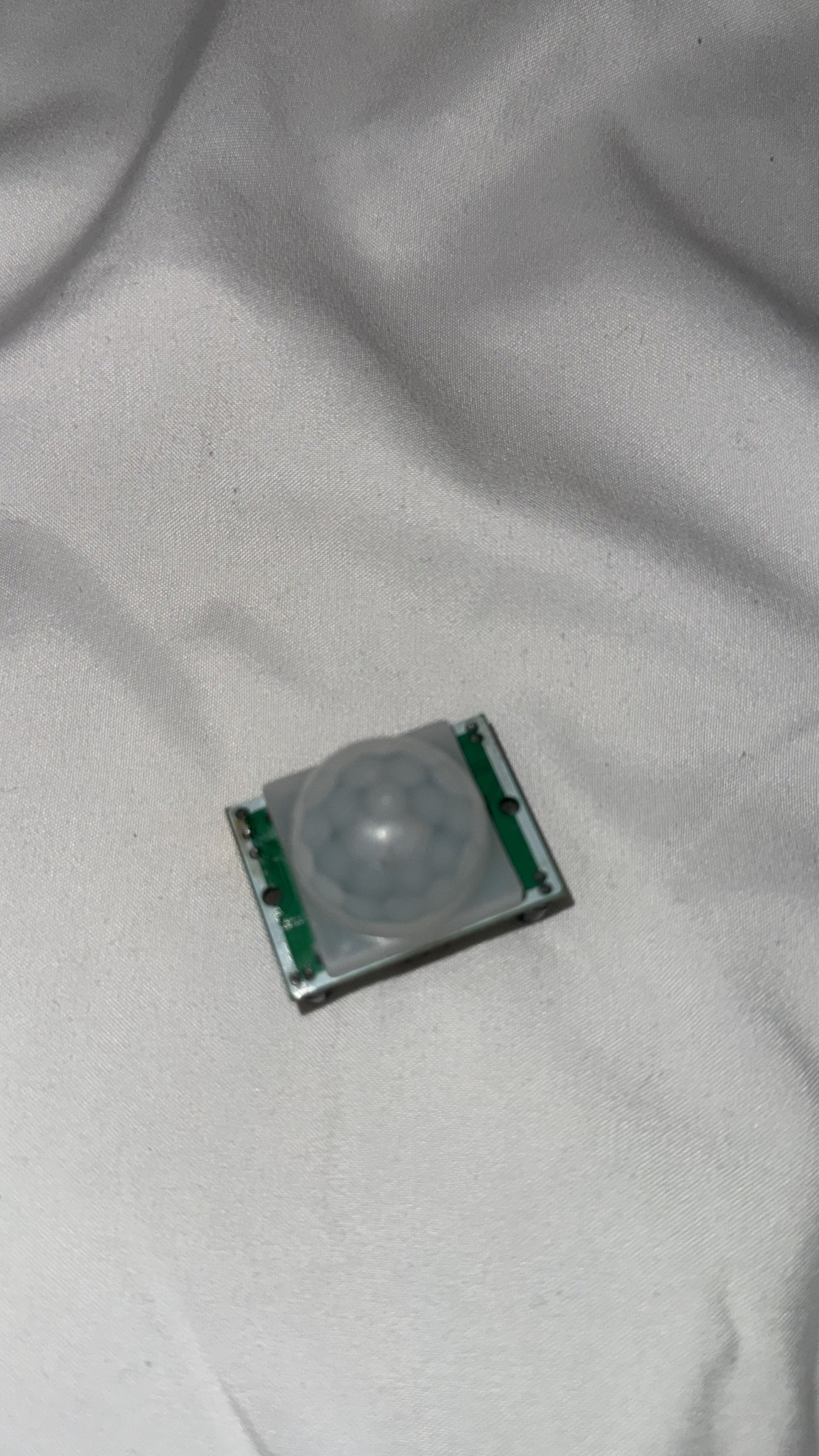
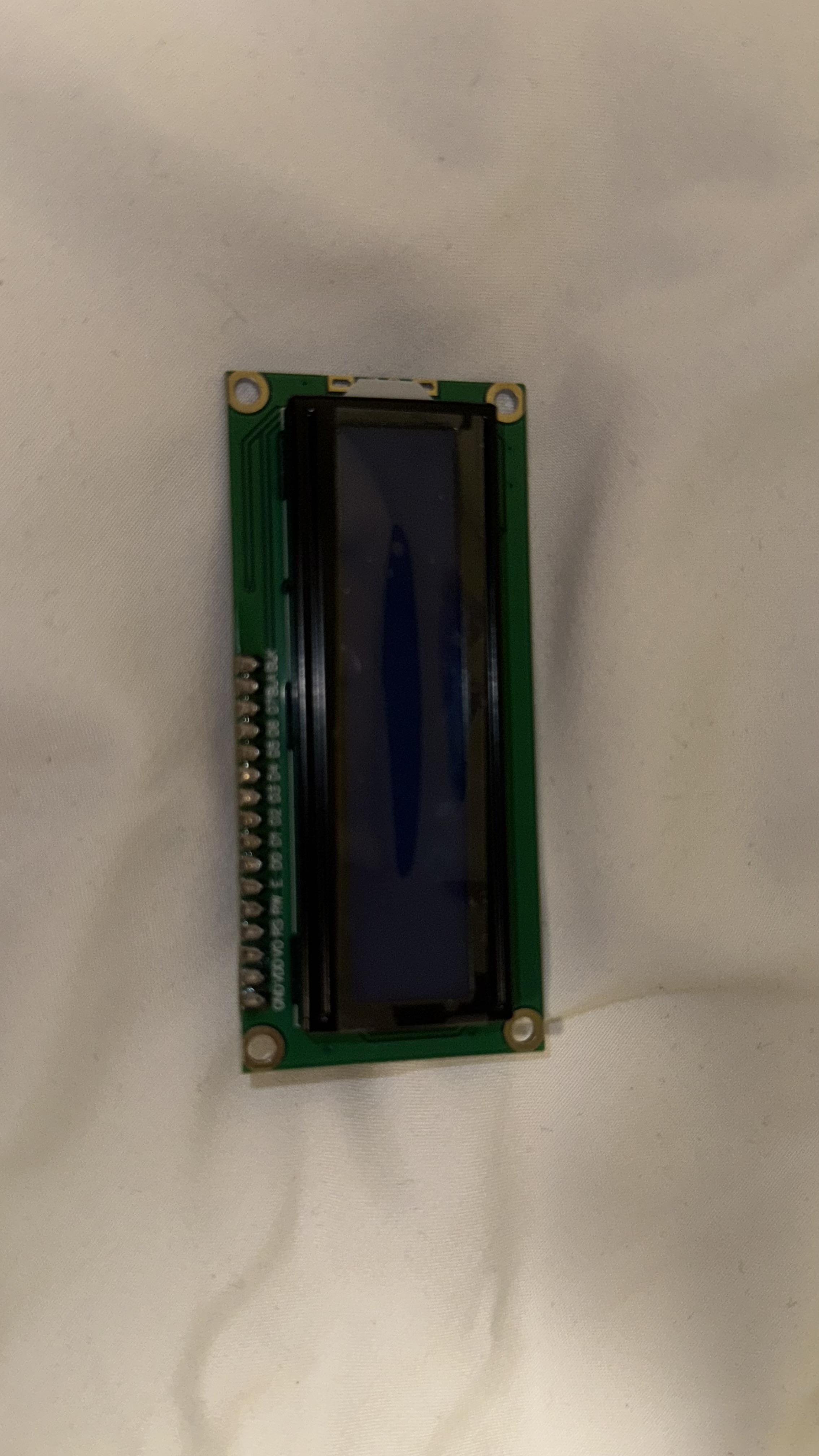
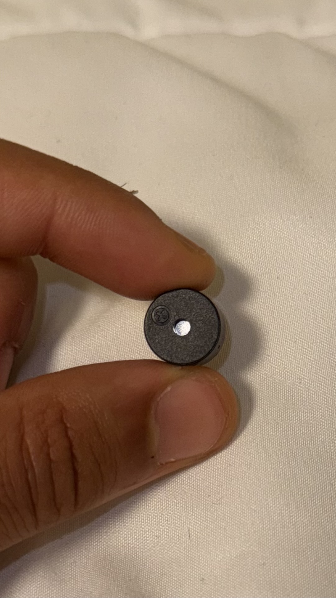
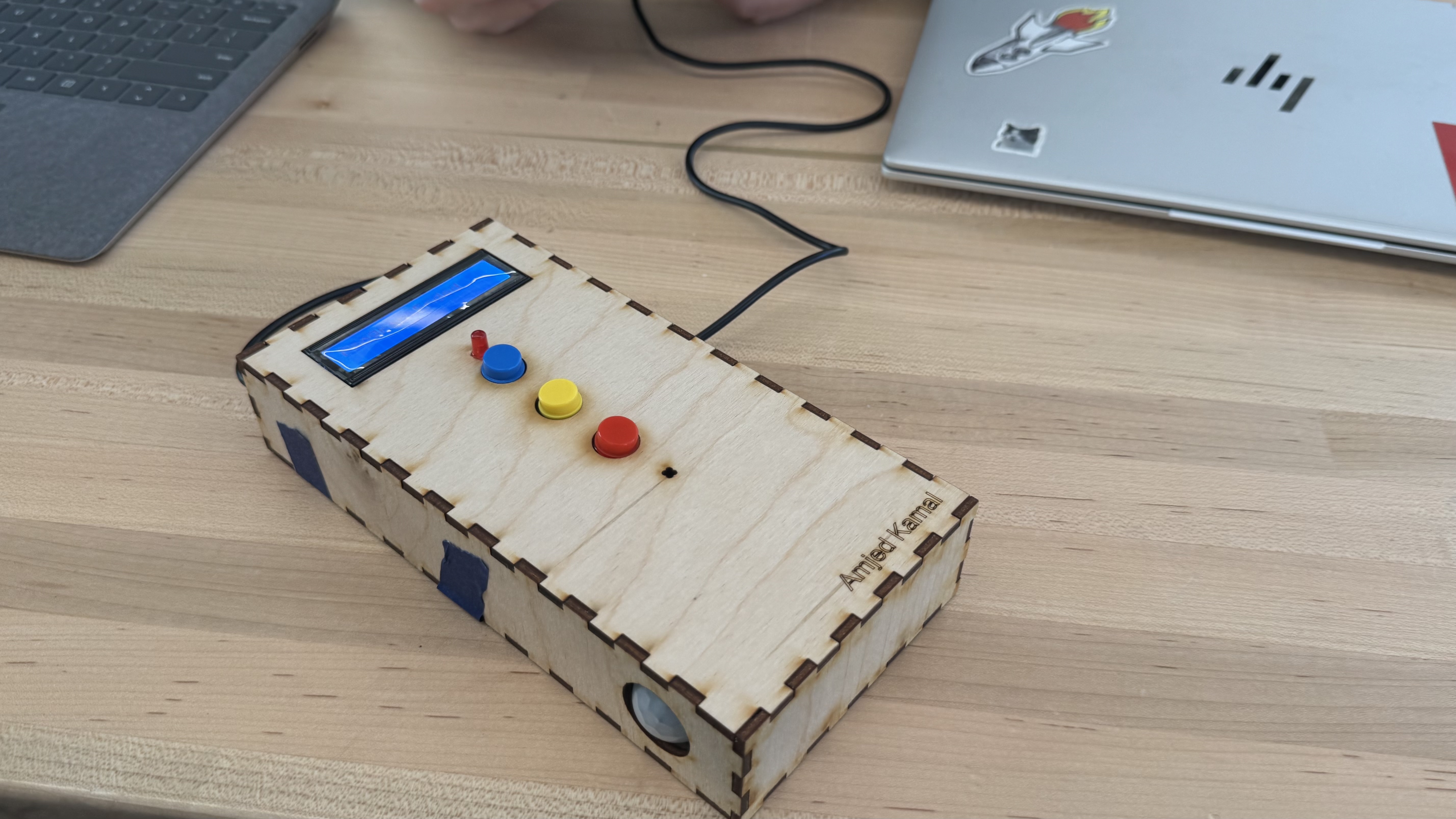
Motion detection comes from one HC-SR501 PIR sensor mounted on the front so it can see through a small circular window.Visual alerts are handled by three bright LEDs (we used a blue, red, and a yellow) and a 16×2 I2C LCD (IIC LCD1602) screen that shows messages like “System Ready,” “ALARM! MOTION!,” or “Wrong Pass!”. User input is three simple push buttons (red, blue, yellow) that double as both the password entry and arm/disarm controls. The audible alarm is an active buzzer driven directly by a PWM pin to make that annoying high-low siren sound. Everything is wired on a standard breadboard first, then soldered onto a prototyping board that fits neatly inside the final box. Power comes from a regular USB cable plugged into the laptop. The enclosure itself is clear plywood, laser-cut from our AutoCAD drawings, held together with glue and tape. Total cost for everything outside the kit was basically zero since the makerspace gave us the plywood and we already had the wires and other materials.
Motion Sensor LCD Screen Buzzer
Design Process:
Prototypes: 
As a team, each member designed their own conceptual layout for the device.
We then compared the designs and collaboratively selected the most functional arrangement. Picking the most optimal was something we were considering for a long time of our project. The final design we selected (the one located at the bottom of the figure) offered the most intuitive interface: the buttons are centered and evenly spaced, the LCD screen is clearly visible at the top, and the PIR motion sensor and buzzer are positioned in a way that maximizes both detection accuracy and alarm audibility.
Additionally, the chosen prototype layout made the wiring easier and helped prevent confusion when operating the system. It was also the easiest design to test, fix, and update as the project moved forward. Working as a team helped us mix creativity with practicality and come up with a solution that reflects our group’s problem-solving process.
As for the other prototype layouts, many of them had issues such as limited wiring space, oversized dimensions, or components that were not arranged precisely. Some designs made it difficult to route wires cleanly, while others required more space than was practical for our enclosure.
After building and testing the first version of our chosen prototype, we also realized that the motion sensor worked better when installed on the side rather than directly on the front. Placing the sensor on the side improved the detection angle, reduced false triggers, and made the overall design easier to position inside a room. For instance, when hidden beside a door, the side-mounted sensor can detect someone entering or even attempting to pick the lock, providing discreet security without being noticeable. This adjustment shows how our prototype continued to evolve as we tested it and learned more about how each component performed in real conditions.
Flowchart:
For the flowchart section, I created my own logic diagram to visualize how the alarm system would operate. This flowchart shows my personal interpretation of how the device should start up, request a password, monitor motion, activate the alarm, and then verify a password to turn it off. Each team member developed their own flowchart based on how they imagined the system working, and this one represents my individual design approach. Creating this helped me understand the full sequence of events and made it easier to think about the coding structure before actually writing it. By laying out decisions such as password correctness, motion detection, button inputs, and alarm states, I was able to see how different parts of the system would interact. Even though the team did not use my entire flowchart as the final reference, it contributed to our overall brainstorming and helped us compare how each design handled logic, user inputs, and alarm conditions.
Wokwi Setup:
Wokwi is an online electronics simulator that lets users build and test virtual circuits using components like sensors, LEDs, buttons, and microcontrollers such as the Raspberry Pi Pico. It runs code in real time, allowing you to plan, debug, and experiment with design ideas before creating the physical prototype.
Using Wokwi was the biggest reason of our success since we had understood how to improve both our code and the wiring for our alarm system. As we ran the simulation, we could see which parts of the code were not responding correctly, when the password was not being saved the right way, or when the PIR sensor was not reading motion properly. Instead of guessing, the simulation showed live messages, button inputs, and alarm states, which made it easier to see exactly what needed to be changed. We also learned how the wiring could be adjusted by seeing how each pin connected to the LCD, buttons, PIR sensor, and buzzer. If a button did not respond or an LED stayed off, we knew that the pin mapping or pull-ups had to be changed. This allowed us to reorganize our wiring, choose better GPIO pins, and understand where each component should be placed on the breadboard before building the real prototype. Wokwi made it clear what the system needed, which helped us rewrite our code, fix bugs faster, and prepare a physical layout that would work correctly the first time.

Cad Design:
The CAD design on the left represents my original prototype layout. I created it to visualize where each component should be placed, including the buzzer, LEDs, buttons, and motion sensor. This first design helped me understand spacing, wiring paths, and how the enclosure would need to be shaped to fit all the parts without crowding. It also gave me a better idea of how large the front panel and mounting holes needed to be so everything could be easily accessed and secured.


The CAD drawing on the right represents the final version that our group agreed on. This final design includes improved spacing, cleaner dimensions, and more precise placement of each component, which made it easier to manufacture and assemble. The screen was centered and enlarged, the motion sensor was given more room at the bottom, and the button and buzzer holes were adjusted for better usability and wiring. By going through multiple iterations, including my own first sketch, we were able to refine the design into a clean and accurate layout that could be used for laser cutting or enclosure fabrication.
Cardboard Prototype:
At this point, we started working together on the final prototype.
After completing our CAD designs and Wokwi simulations, we built a physical prototype using
cardboard to represent the enclosure. The goal of this prototype was not to perfectly match the final materials, but to test the layout, spacing, and usability of the front panel before moving to more
permanent fabrication. The cardboard model allowed us to place all the main components in their
intended positions, including the LCD screen at the top, three buttons in the center, the LED indicator,
and the motion sensor at the bottom.
Seeing the prototype in real size helped us confirm that the spacing between buttons was comfortable and that the motion sensor had a clear field of view when the device was positioned near a door. It also helped us visualize how wiring would run inside the box and where structural supports would be needed to secure the electronics. Even though this was an
early version, building it physically gave us a better understanding of how the enclosure would look, how users would interact with it, and what adjustments we would eventually need to make for the final build.
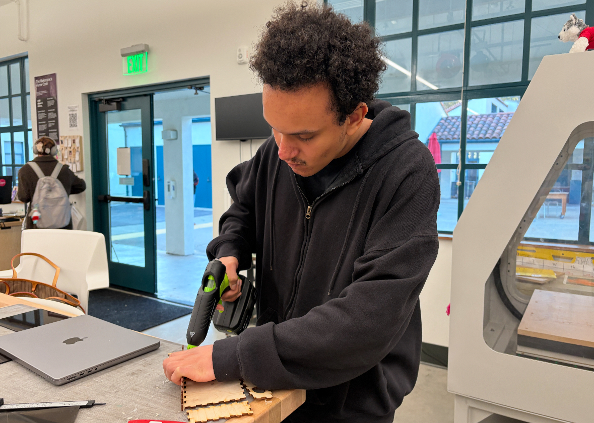
Laser cutting:
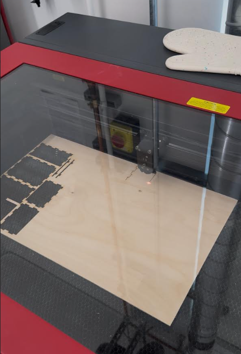 After finalizing our CAD dimensions, we transferred the enclosure design to a laser cutter and fabricated the housing using thin plywood. The laser cutter allowed us to create precise openings for the LCD screen, buttons, LED, buzzer, and motion sensor, as well as clean finger-joint edges that made assembly easy and accurate.
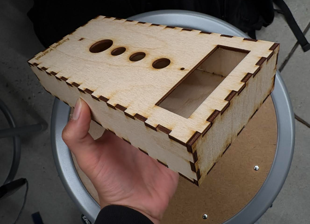 This process helped us turn the digital model into a real, sturdy prototype that matched our measurements exactly, unlike the earlier cardboard version. We completed the cutting and assembly in the campus makerspace, where we could quickly adjust settings, reprint pieces if needed, and ensure all components aligned correctly before installing the electronics.
My Contributions:
 LCD Screen:
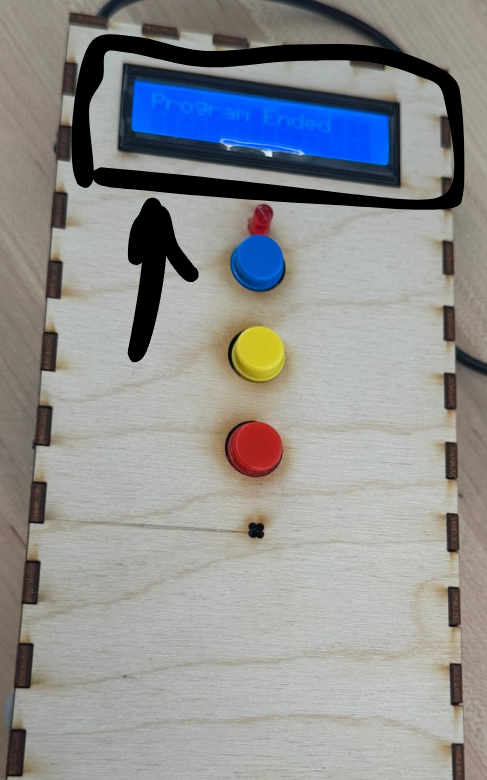
I spent time wiring and configuring the LCD screen to make sure it worked properly with the Raspberry Pi Pico and the rest of the alarm system. First, I had to identify the correct pins for I2C communication, which required testing different connections until the display responded correctly. Once the wiring was stable, I adjusted the code so the screen could show system states such as “System Ready,” password entries, motion alerts, and finally “Program Ended,” as seen in the photo. Getting the LCD to fit inside the enclosure also required careful routing of wires so they would not pull loose when the box was closed. By experimenting with both the wiring and the program output, I made sure the display was readable, updated at the right moments, and functioned as one of the main user interfaces of the prototype.
I controlled the LCD screen using I2C communication. In the code, I2C(0, sda=Pin(0), scl=Pin(1), freq=400000) sets up the I2C connection, and i2c.scan()[0] finds the address of the LCD automatically. Then I2cLcd(i2c, I2C_ADDR, 2, 16) creates the LCD object so the program can write text to the 2x16 display.
Wiring:
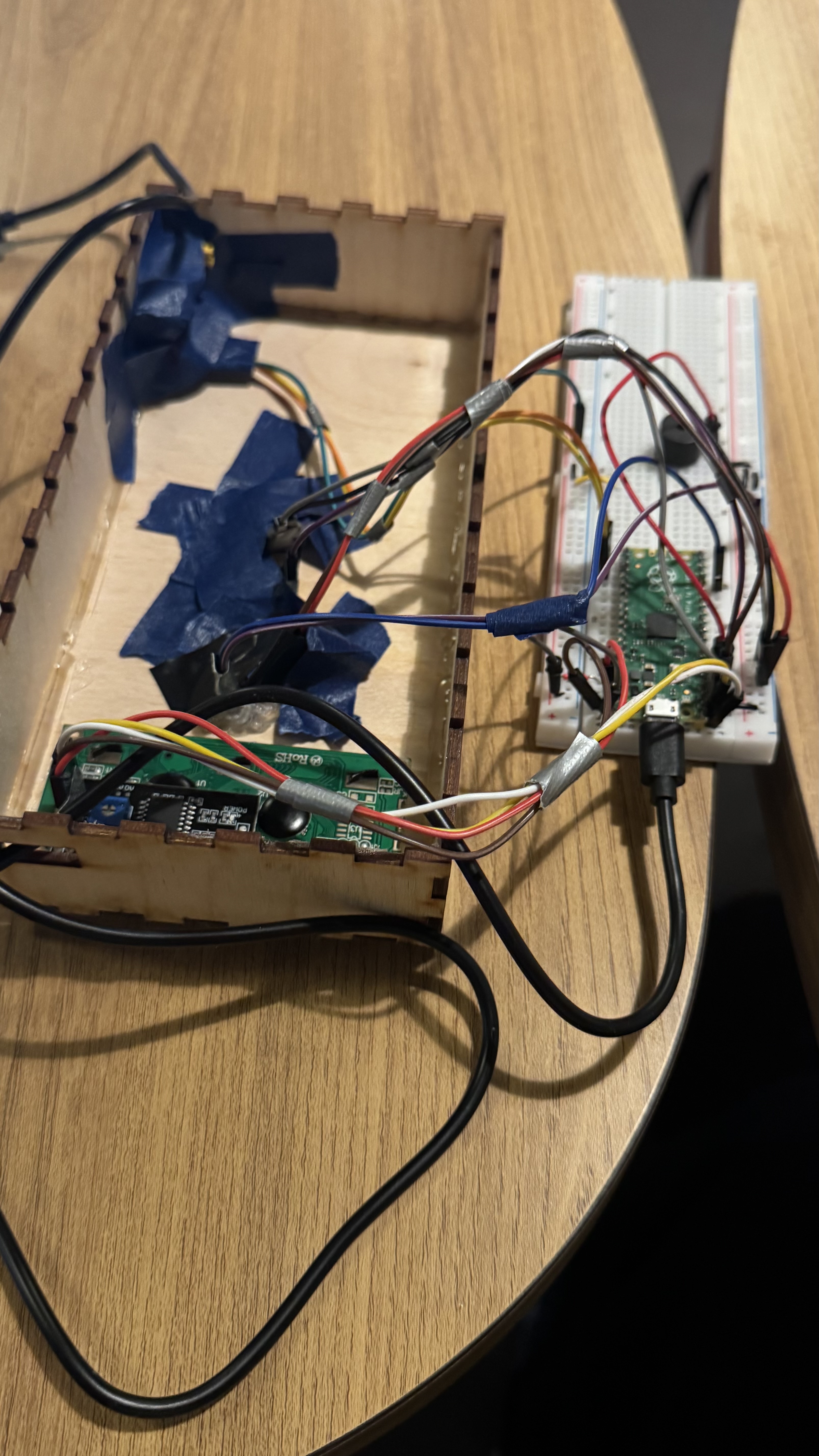
Once the enclosure was ready, we began wiring the components inside the box and connecting them to the breadboard and Raspberry Pi Pico. During assembly, we noticed that some wires were getting tangled or taking up too much space, so we taped groups of wires together to keep them organized and reduce clutter. This small step made the prototype easier to work with, since it prevented wires from shifting when closing the enclosure and made troubleshooting faster. As a result, the wiring layout became more efficient, easier to access, and less likely to get pulled or disconnected during testing and movement.
My Personal Reflection:
Looking back at the project, I think one of the biggest challenges in our design was the buzzer. It did not sound as loud as we originally expected, and as a group we realized that it would have been better if we had mounted the buzzer sticking out of the enclosure instead of keeping it inside. That would have helped the sound travel more clearly and made the alarm easier to hear from a distance. 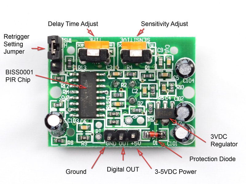
As a group, we were also challenged by the PIR motion sensor because it sometimes lagged or did not trigger right away. The way we fixed that was through readjusting the delay timing option in the back of the motion sensor with a screw as shown in the picture. As for the trigger lag, we also did the same thing with the other option of adjustment. Even though these challenges were frustrating at times, they helped us learn more about real-world prototyping and how design decisions affect the way a system works.
 As a group, there are a few changes we would make in a future version of the alarm system. One improvement would be adding a password reset button, which would make it easier to manage access without having to reprogram the system. We would also consider adding a short delay in the code before the system shuts down completely, the timing of the delay can be showcased on the screen instead of turning off right away and requiring the user to restart and reset everything from the beginning. These adjustments would make the alarm more user-friendly and less repetitive when testing or operating it multiple times.
As part of presenting the work we received positive feedback such as:
"I really like the idea and set up and the correct password and motion sensor idea"
"The project looks creative and well designed"
Some other feedback for the future we received were like:
"Remove tapes from the side", "reliability of the PIR sensor might be tough in the future", and "You should be able to change the password". All these feedback were very helpful in our discussion afterwards and helped us think of things we could add in the future if worked on again.
Overall, this project was a great learning experience. I was able to work with coding, the Raspberry Pi Pico, electronic components, and enclosure design all at once, which helped me understand how hardware and software come together in a real prototype. I also gained communication and teamwork skills, especially when we had to combine ideas, solve wiring issues, divide tasks, and make design decisions as a group. The hands-on process, from coding to building to testing, made the experience valuable and enjoyable, and it gave me confidence in working with both electronics and collaborative engineering projects.
Ethical Considerations:
Our home invasion device reflects values of safety, accessibility, and giving users more control over their personal environment. The technology introduces a new practice where low-cost, homemade security systems can become part of everyday life, encouraging people to build, customize, and understand their own devices rather than relying only on commercial products. From a life-cycle perspective, we went through several prototypes and learned that manufacturing electronics involves materials like metals, plastics, and chips that require mining, processing, and eventually disposal, which can contribute to waste if not recycled properly. Overall, the project helped us explore how technology affects society and how society’s needs and values shape the way devices are designed, built, and used.
Acknowledgements:
I would like to thank my classmates that worked on this with me: Amjed, Micah, and Tony. I would also like to thank my professor, Leila Keyvani, for teaching us and providing support whenever needed. Lastly, I would like to thank the Northeastern Oakland Makerspace for providing the tools, devices, and materials needed to complete the project.
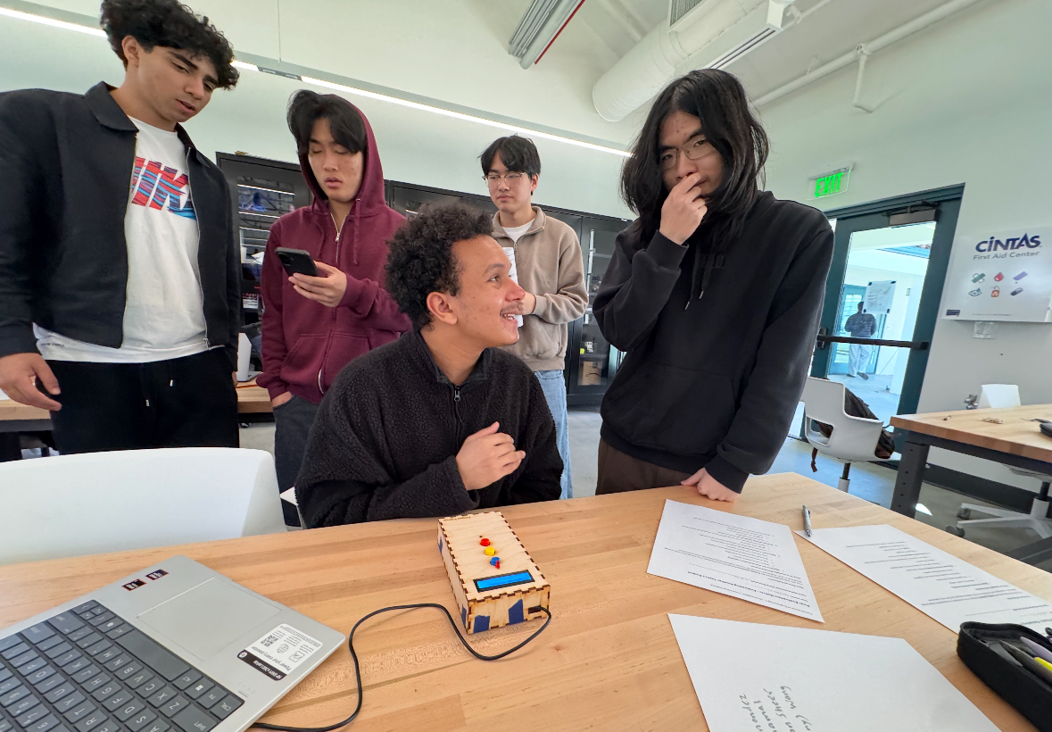
Demonstration of Project:
Code Used for Device:
from machine import I2C, Pin, PWM
from pico_i2c_lcd import I2cLcd
from picozero import Button, LED
from time import sleep


# LCD Setup

i2c = I2C(0, sda=Pin(0), scl=Pin(1), freq=400000)
I2C_ADDR = i2c.scan()[0]
lcd = I2cLcd(i2c, I2C_ADDR, 2, 16)


# LED + Buzzer

led = LED(13)
led.off()  # make sure LED is off at start

buzzer = PWM(Pin(5))
buzzer.duty_u16(0)


# Buttons
button_red = Button(2, pull_up=True)
button_blue = Button(3, pull_up=True)
button_yellow = Button(4, pull_up=True)


# PIR Sensor on GP16
pir = Pin(16, Pin.IN)

# Password
PASSWORD = ["red", "blue", "yellow"]
entered = []
alarm_on = False
siren_state = False

lcd.clear()
lcd.putstr("System Ready")
sleep(1)


# Main Loop
while True:

    pir_value = pir.value()

    # Detect motion anytime

    if pir_value == 1 and not alarm_on:
        alarm_on = True
        entered = []
        led.on()  # LED lights after motion is detected
        lcd.clear()
        lcd.putstr("ALARM! MOTION!")
        sleep(0.2)

    # Alarm is active
    if alarm_on:

        # Non-blocking siren
        siren_state = not siren_state
        if siren_state:
            buzzer.freq(1800)
        else:
            buzzer.freq(2300)
        buzzer.duty_u16(50000)

        # Button Input
        if button_red.is_pressed:
            entered.append("red")
            lcd.clear()
            lcd.putstr("RED")
            sleep(0.3)

        if button_blue.is_pressed:
            entered.append("blue")
            lcd.clear()
            lcd.putstr("BLUE")
            sleep(0.3)

        if button_yellow.is_pressed:
            entered.append("yellow")
            lcd.clear()
            lcd.putstr("YELLOW")
            sleep(0.3)

        # Check password
        if len(entered) == len(PASSWORD):

            if entered == PASSWORD:
                # Correct password: turn everything off and EXIT program
                lcd.clear()
                lcd.putstr("Password OK")
                buzzer.duty_u16(0)
                led.off()
                sleep(1)

                lcd.clear()
                lcd.putstr("System Off")
                sleep(1)

                # kill the code (exit the while True loop)
                break

            else:
                lcd.clear()
                lcd.putstr("Wrong Pass!")
                entered = []
                sleep(1)
                lcd.clear()
                lcd.putstr("Try Again")
                sleep(0.5)

    else:
        # Alarm off (before motion or after reset)
        buzzer.duty_u16(0)
        led.off()

    sleep(0.05)  # Very important for PIR stability


# After loop exits

buzzer.duty_u16(0)
buzzer.deinit()
led.off()
lcd.clear()
lcd.putstr("Program Ended")
Citations:
SafeHome. (2023). Home security statistics and data insights. SafeHome.org. https://www.safehome.org/data/home-security-statistics/
Adafruit Industries. (n.d.). PIR motion sensor tutorial. Adafruit Learning System. https://learn.adafruit.com/pir-passive-infrared-proximity-sensor
Wokwi. (2024). Raspberry Pi Pico simulator. https://wokwi.com
U.S. Environmental Protection Agency. (2023). Electronics waste and recycling. EPA.gov. https://www.epa.gov/recycling-electronics